Brick straightening and loading machine

A car loading machine and component technology, applied in the field of brick car loading machine, achieves the effects of fast speed, easy rotation, and simple structural design

Pending Publication Date: 2018-11-02
王景信
View PDF8 Cites 0 Cited by
  • Summary
  • Abstract
  • Description
  • Claims
  • Application Information

AI Technical Summary

Problems solved by technology

There is no special equipment that can solve this problem in the prior art

Method used


Image

  • Brick straightening and loading machine
  • Brick straightening and loading machine

Examples


Embodiment Construction

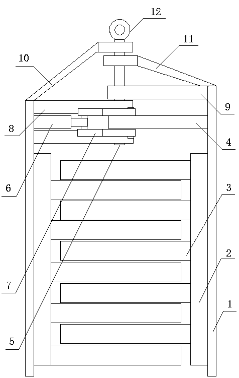
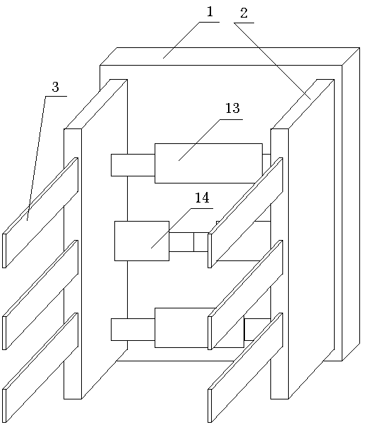
[0014] like figure 1 , 2 As shown, a brick straightening loading machine includes a clamp arm assembly I and a clamp arm assembly II, a hinge assembly connecting the clamp arm assembly I and the clamp arm assembly II, and a hydraulic control assembly. The hinge assembly is installed on the clamp arm assembly I and the top of the clamp arm assembly II, and make the clamp arm assembly I and the clamp arm assembly II rotate with the hinge assembly; the clamp arm assembly I includes a main frame plate 1, two auxiliary frame plates 2 and several clamp arms 3, in At least two sliding sleeves 13 are arranged on the main frame plate 1, and two sub-frame plates 2 are installed on both sides of the sliding sleeves 13, and are connected with the sliding sleeves through sliding rods, and several clamping arms 3 are symmetrically installed on the two sub-frame plates 2 respectively. , at least one pair of hydraulic cylinders 14 are set between the two sub-frame plates 2, and the piston ro...


PUM


Abstract

The invention discloses a brick straightening and loading machine which comprises a clamping arm assembly I, a clamping arm assembly II, a pivot assembly for connecting the clamping arm assembly I andthe clamping arm assembly II, and a hydraulic control assembly. The pivot assembly is arranged on the top parts of the clamping arm assembly I and the clamping arm assembly II, so that the clamping arm assembly I and the clamping arm assembly II can rotate around the pivot assembly; the clamping arm assembly I and the clamping arm assembly II have the same structure, but a clamping arm on the clamping arm assembly I and a clamping arm on the clamping arm assembly II are arranged in an intermeshing way; the pivot assembly comprises a pushing and rotating hydraulic cylinder; one end is fixed onto any one connecting plate; a piston rod is connected to one end of an arc-shaped pull rod; the other end of the arc-shaped pull rod is connected with another connecting plate; and under the pushingof the pushing and rotating hydraulic cylinder, the clamping arm assembly I and the clamping arm assembly II are rotated to one straight line. The brick straightening and loading machine provided by the invention is simple in structure design, can be operated by one person, is high in efficiency and fast in speed, only requires 10 more minutes for loading one car of bricks, and is greatly reducedin cost compared with manual loading.

Description

technical field [0001] The invention relates to a brick loading machine, in particular to a brick straightening loading machine. Background technique [0002] During the firing process of bricks, two adjacent rows are placed vertically and intersecting, so that the bricks can be burned thoroughly and placed firmly. Therefore, the existing brick making machine naturally arranges the bricks in this way after they are produced. . But in this way, after the bricks are fired into red bricks, there is a problem that is difficult to solve. It cannot be loaded by machinery. The bricks stacked in multiple layers and columns need to be placed in one direction when loading. Manpower, relying on manpower is not only costly, but also extremely inefficient. [0003] For this kind of loading work, the equipment is required to be easy to operate, long in service life and low in price. There is not a kind of special equipment that can solve this problem in the prior art. Contents of the...

Claims


Application Information

Patent Timeline
Patent Type & Authority Applications(China)
IPC IPC(8): B28B17/00
CPCB28B17/00
Inventor 王景信
Owner 王景信
Why Eureka
Try Eureka