Pantograph traction device of track train

A technology for pulling devices and rail trains, applied in current collectors, electric vehicles, vehicle components, etc., can solve the problems of low measurement accuracy of pantograph relaxation force, achieve the effects of improving assembly efficiency, compact structure, and enhancing calibration accuracy

Active Publication Date: 2018-11-02
ZHENGZHOU RAILWAY VOCATIONAL & TECH COLLEGE
View PDF12 Cites 0 Cited by
  • Summary
  • Abstract
  • Description
  • Claims
  • Application Information

AI Technical Summary

Problems solved by technology

[0004] The purpose of the present invention is to provide a pantograph pulling device for rail trains, which solves the problem of low measurement accuracy of the pantograph relaxation force caused by the difficulty of keeping the pantograph at the measurement position in the prior art

Method used


Image

  • Pantograph traction device of track train
  • Pantograph traction device of track train
  • Pantograph traction device of track train

Examples


Embodiment Construction

[0029] Embodiments of the present invention will be further described below in conjunction with the accompanying drawings.

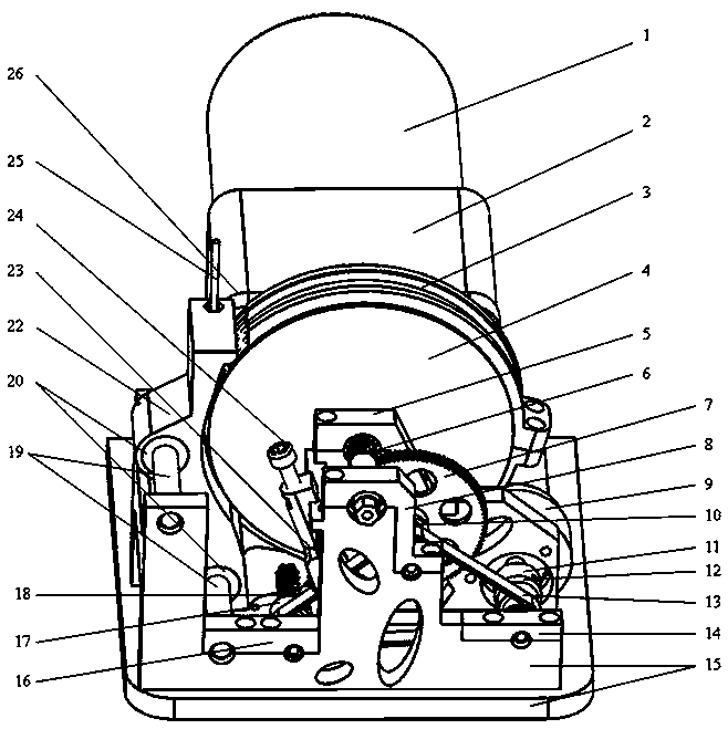
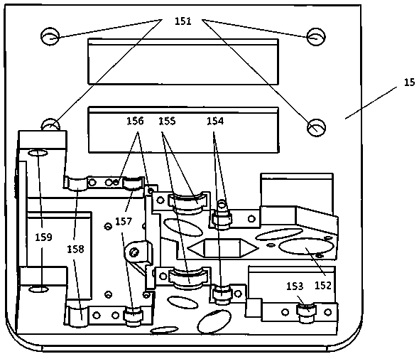
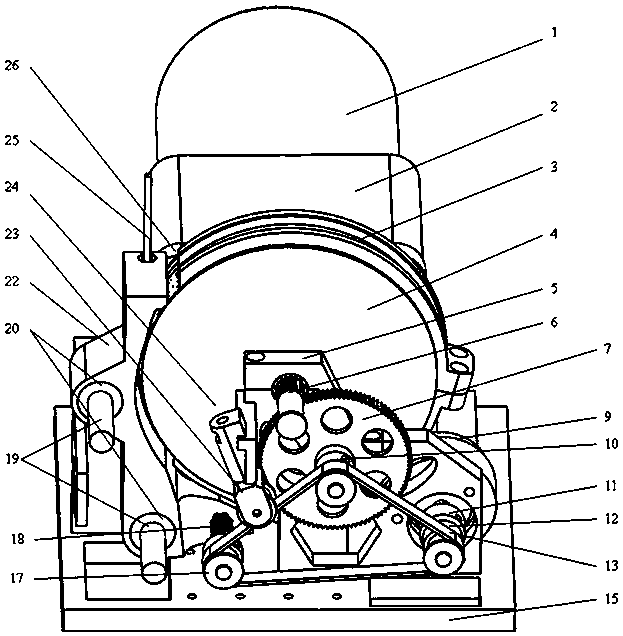
[0030] Specific embodiment one of rail train pantograph pulling device of the present invention, as Figure 1 to Figure 4 As shown, a mounting base 15 is included, and a driving mechanism is installed on the front half of the mounting base 15 through a mounting hole 151 , and the driving mechanism includes a driving motor 1 and a reducer 2 . In this embodiment, the second half of the mounting base 15 is equipped with a synchronous combination unit composed of a cable straightener 22, a rotary potentiometer 9 and a reduction mechanism integrated through a fixed frame, and the fixed frame includes front and rear frames arranged at intervals. body.

[0031] The output shaft of the speed reducer of the driving mechanism is equipped with a winding wheel 4, which is provided with a spiral winding groove on the peripheral surface of the winding wheel 4. The gr...


PUM


Abstract

The invention relates to a pantograph traction device of a track train. The pantograph traction device of the track train comprises a mounting base, a wire winding wheel is rotatably assembled on themounting base and provided with a spiral wire winding groove, the side, at the wire winding wheel, of the mounting base is provided with a wire discharging device, the wire discharging device is provided with a wire discharging channel and connected with a wire discharging device driving device, and the wire discharging device driving device is provided with a power input shaft; the mounting baseis provided with a speed reduction mechanism, the speed reduction mechanism is provided with an output shaft, and when the wire winding wheel rotates within a full number of turns, the rotation angleof the output shaft is always less than 360 degrees; the mounting base is further provided with a rotary potentiometer, the output shaft of the speed reduction mechanism, a power input shaft of the wire discharging device driving device and an input shaft of the rotary potentiometer are connected through transmission pieces to achieve the constant-angular-velocity and synchronous movement of the output shaft of the speed reduction mechanism, the wire discharging device and the rotary potentiometer. According to the pantograph traction device of the track train, a traction line can accurately stay at a detection position, and the accuracy of measuring the pantograph relaxation force is improved.

Description

technical field [0001] The invention relates to a rail train pantograph pulling device. Background technique [0002] At present, with the rapid increase in the mileage of my country's ordinary railways, high-speed railways, and urban rail lines, the number of rail trains has grown rapidly. As an important part of the electric locomotive, the pantograph is used to transmit the electric energy transmitted by the catenary to the traction power of the locomotive and other battery modules. When working, the pantograph will maintain a certain distance with the catenary under the action of pressure such as air pressure. Pressure to ensure that the carbon slider of the pantograph is in good contact with the catenary. Therefore, the tension force of the pantograph is one of the important parameters to measure whether the pantograph works normally or not. At present, the known pantograph force-measuring devices for rail trains are mainly hand-held force-measuring devices, which gen...

Claims


Application Information

Patent Timeline
Patent Type & Authority Applications(China)
IPC IPC(8): B60L5/20
CPCB60L5/20
Inventor 徐彦赵嵩焦阳吕蒙牛晨旭王云飞陈静远吴安伟王欢欢李潇潇
Owner ZHENGZHOU RAILWAY VOCATIONAL & TECH COLLEGE
Why Eureka
Try Eureka