Rotating plate type automatic loading machine for glass tubes

An automatic feeding and glass tube technology, applied in glass production, glass molding, glass re-molding, etc., can solve problems such as difficulty in hiring workers, high labor intensity, and high labor cost pressure for enterprises

Inactive Publication Date: 2018-11-02
黎泽新
View PDF0 Cites 4 Cited by
  • Summary
  • Abstract
  • Description
  • Claims
  • Application Information

AI Technical Summary

Problems solved by technology

At present, the machine is manually inserted into the fixture one by one to load the materials in China. It is not only necessary for the workers to be skilled in operating technology to complete the intubation action at one time.
Moreover, the operating environment is very high temperature and the labor intensity is high, which makes it very difficult for the entire industry to hire workers for this type of work. Moreover, the current labor cost is increasing year by year, causing great pressure on the labor cost of enterprises.

Method used


Image

  • Rotating plate type automatic loading machine for glass tubes
  • Rotating plate type automatic loading machine for glass tubes
  • Rotating plate type automatic loading machine for glass tubes

Examples


Embodiment Construction

[0029] In order to make the purpose, technical solutions and advantages of the present invention more clear, the technical solutions in the embodiments of the present invention will be clearly and completely described below in conjunction with the accompanying drawings and embodiments, and in conjunction with the accompanying drawings in the embodiments of the present invention. Apparently, the described embodiments are only some of the embodiments of the present invention, but not all of them. Based on the embodiments of the present invention, all other embodiments obtained by persons of ordinary skill in the art without creative efforts fall within the protection scope of the present invention.

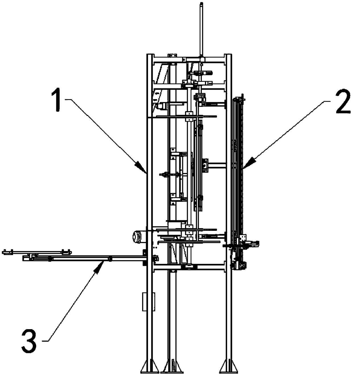
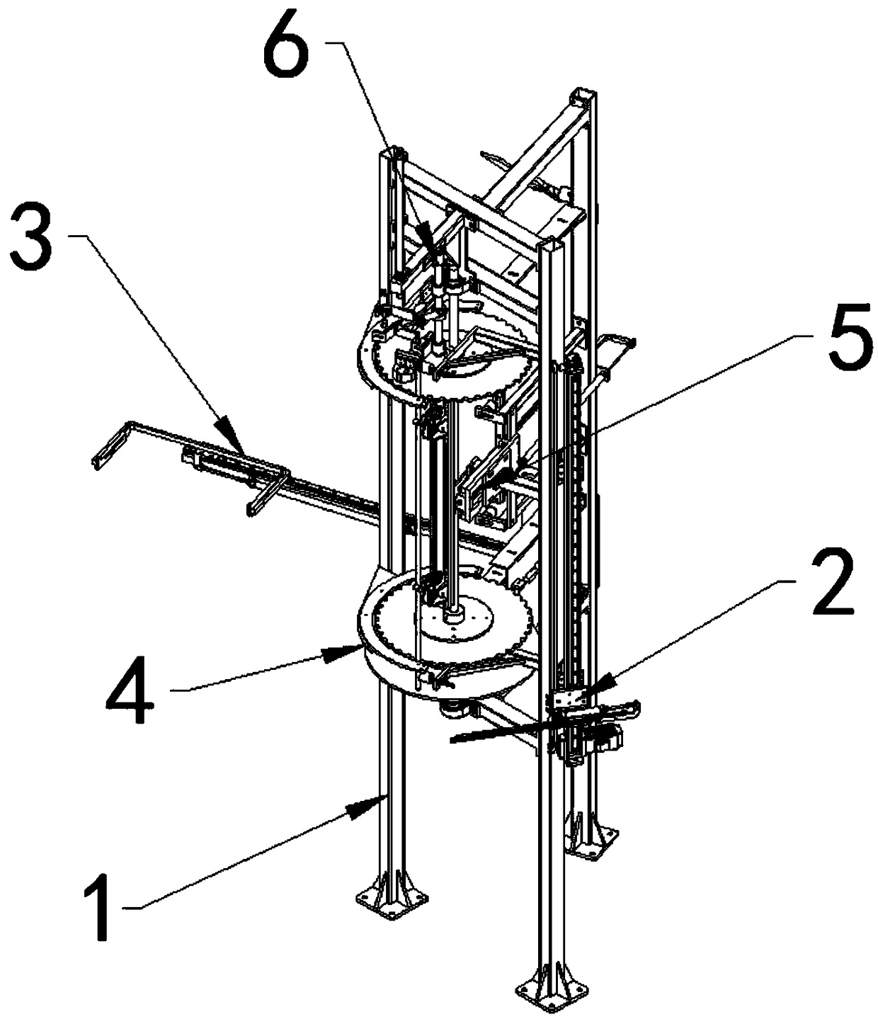
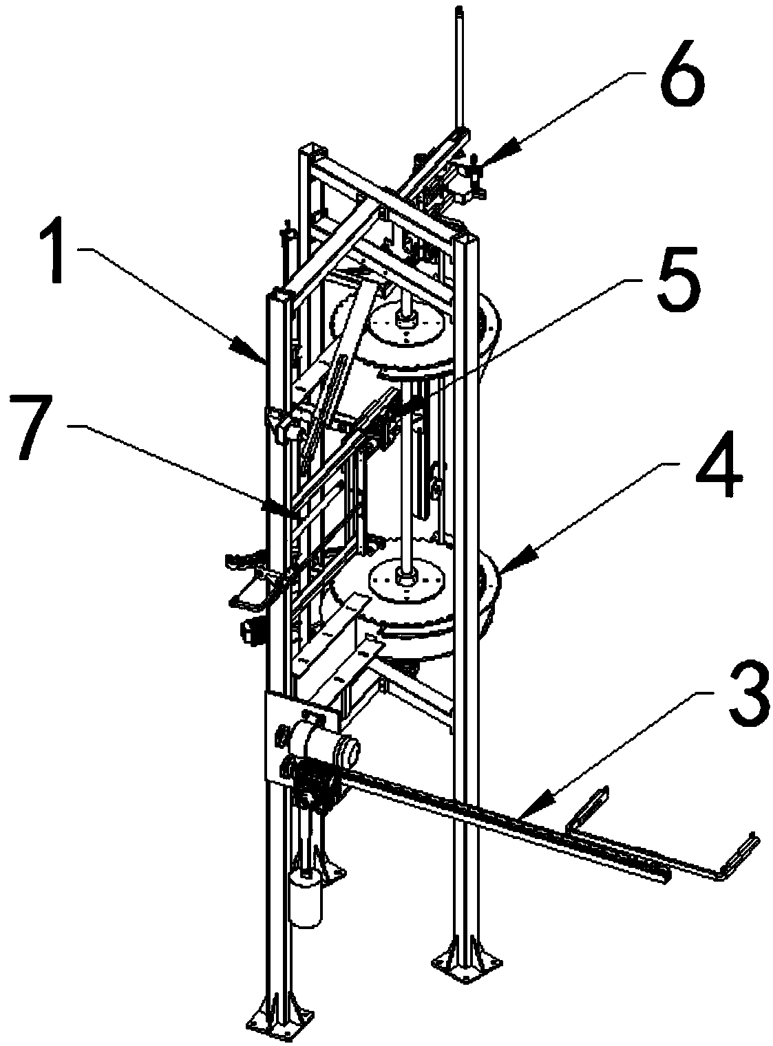
[0030] Such as figure 1 , figure 2 , image 3 with Figure 4 As shown, in order to solve the above-mentioned technical problems, the technical solution adopted in the present invention is: a kind of rotary table type glass tube automatic feeding machine, comprises frame 1 and bl...


PUM


Abstract

The invention discloses a rotating plate type automatic loading machine for glass tubes. The rotating plate type automatic loading machine for the glass tubes comprises a rack, a glass tube overturning device, a pushing tube conveying device, a rotating plate separating device, a pushing tube inserting device, a blowing head and tube tail butt joint device and a blowing head lifting device, and the glass tube overturning device, the pushing tube conveying device, the rotating plate separating device, the pushing tube inserting device, the blowing head and tube tail butt joint device and the blowing head lifting device are separately mounted on the rack. During use, glass tubes from a previous procedure can be erected by the glass tube overturning device, then the glass tubes are conveyed into slots of an upper rotating plate and a lower rotating plate of the rotating plate separating device one by one through the pushing tube conveying device and are orderly arranged in a separated manner, then the glass tubes are conveyed into the pushing tube inserting device one by one by rotation of the rotating plate and are conveyed to positions above an object equipment clamp one by one, theglass tubes are in butt joint with blowing heads by the blowing head and tube tail butt joint device and then are conveyed into the object equipment clamp, before the glass tubes are in butt joint with the blowing heads, the blowing heads are lifted up in advance necessarily through the blowing head lifting device, and then, tube inserting actions are finished. Therefore, ordered production is implemented, a large number of labor costs are saved, requirements for automatic production are met, and the production efficiency is greatly improved.

Description

technical field [0001] The invention relates to the technical field of glass tube production equipment, in particular to a turntable glass tube automatic feeding machine. Background technique [0002] At present, bulb shells, various handicrafts, and controlled oral liquid bottles produced by glass tubes are basically produced by adopting a rotary table type vertical machine (abbreviated as "bubbler") and a bottle making machine. And this machine all is to adopt manually to insert in the fixture one by one to load at present domestically, not only must the skilled operation technology of the worker just can complete intubation action at one time. Moreover, the operating environment is very high temperature and the labor intensity is high, which makes it very difficult for the entire industry to hire workers for this type of work. Moreover, the current labor cost is increasing year by year, causing great pressure on the labor cost of enterprises. Based on the actual situatio...

Claims


Application Information

Patent Timeline
Patent Type & Authority Applications(China)
IPC IPC(8): C03B23/07
CPCC03B23/07Y02P40/57
Inventor 黎泽新
Owner 黎泽新
Why Eureka
Try Eureka