Ditching equipment for burying a petroleum pipeline underground

A technology for oil pipelines and equipment, applied in the field of trenching equipment, which can solve problems such as dust influence, high labor intensity, and slow trenching speed

Inactive Publication Date: 2018-11-02
方蓉芳
View PDF5 Cites 4 Cited by
  • Summary
  • Abstract
  • Description
  • Claims
  • Application Information

AI Technical Summary

Problems solved by technology

[0004] In order to overcome the shortcomings of high labor intensity, slow ditching speed, and dust that easily affects the surrounding environment when digging the land manually, the purpose of the present invention is to provide a low labor intensity, fast ditching speed, digging Dust is not easy to appear when trenching, and trenching equipment for buried oil pipelines that does not affect the surrounding environment

Method used


Image

  • Ditching equipment for burying a petroleum pipeline underground
  • Ditching equipment for burying a petroleum pipeline underground
  • Ditching equipment for burying a petroleum pipeline underground

Examples


Embodiment 1

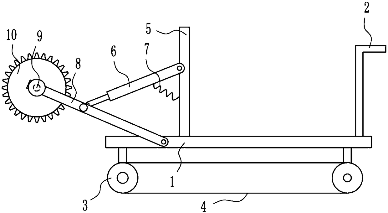
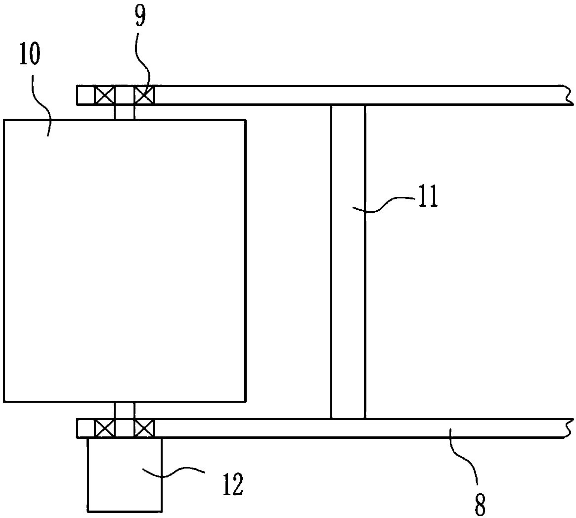
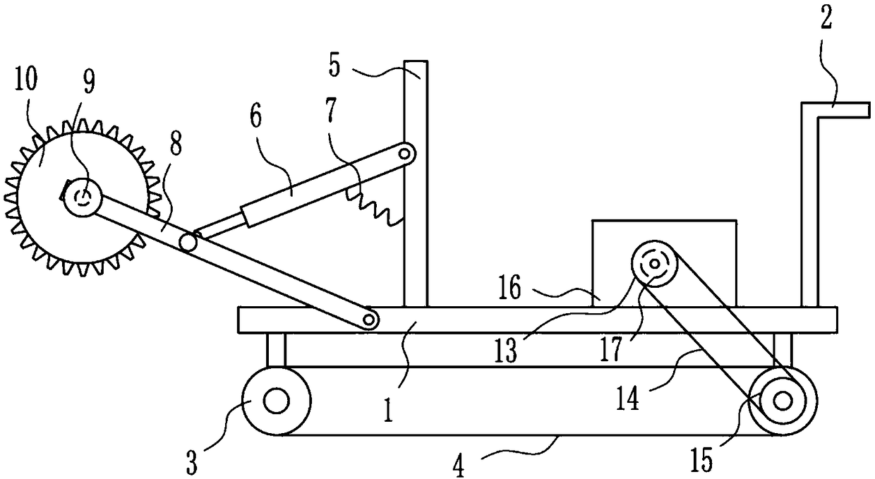
[0022] A kind of trenching equipment for buried oil pipeline, such as Figure 1-5 As shown, it includes base plate 1, push handle 2, sprocket wheel 3, chain belt 4, vertical rod 5, cylinder 6, first spring 7, movable plate 8, first bearing seat 9, crushing wheel 10, connecting rod 11 and the first A motor 12, a push handle 2 is installed on the right side of the top of the base plate 1, a sprocket 3 is installed symmetrically on the left and right sides of the bottom of the base plate 1, and a chain belt 4 is connected between the sprockets 3 on the left and right sides, and the left side of the front side of the base plate 1 and The left side of the back side is rotatably equipped with a movable plate 8, and a connecting rod 11 is installed between the left side of the movable plate 8 on the front and rear sides, and the first bearing seat is installed on the left side of the movable plate 8 on the front and rear sides. 9. A crushing wheel 10 is connected between the first be...

Embodiment 2

[0024] A kind of trenching equipment for buried oil pipeline, such as Figure 1-5As shown, it includes base plate 1, push handle 2, sprocket wheel 3, chain belt 4, vertical rod 5, cylinder 6, first spring 7, movable plate 8, first bearing seat 9, crushing wheel 10, connecting rod 11 and the first A motor 12, a push handle 2 is installed on the right side of the top of the base plate 1, a sprocket 3 is installed symmetrically on the left and right sides of the bottom of the base plate 1, and a chain belt 4 is connected between the sprockets 3 on the left and right sides, and the left side of the front side of the base plate 1 and The left side of the back side is rotatably equipped with a movable plate 8, and a connecting rod 11 is installed between the left side of the movable plate 8 on the front and rear sides, and the first bearing seat is installed on the left side of the movable plate 8 on the front and rear sides. 9. A crushing wheel 10 is connected between the first bea...

Embodiment 3

[0027] A kind of trenching equipment for buried oil pipeline, such as Figure 1-5 As shown, it includes base plate 1, push handle 2, sprocket wheel 3, chain belt 4, vertical rod 5, cylinder 6, first spring 7, movable plate 8, first bearing seat 9, crushing wheel 10, connecting rod 11 and the first A motor 12, a push handle 2 is installed on the right side of the top of the base plate 1, a sprocket 3 is installed symmetrically on the left and right sides of the bottom of the base plate 1, and a chain belt 4 is connected between the sprockets 3 on the left and right sides, and the left side of the front side of the base plate 1 and The left side of the back side is rotatably equipped with a movable plate 8, and a connecting rod 11 is installed between the left side of the movable plate 8 on the front and rear sides, and the first bearing seat is installed on the left side of the movable plate 8 on the front and rear sides. 9. A crushing wheel 10 is connected between the first be...


PUM


Abstract

The invention relates to ditching equipment, in particular to ditching equipment for burying a petroleum pipeline underground. The invention aims to provide the ditching equipment for burying the petroleum pipeline underground which is low in labor intensity, fast in ditching speed, and not easy to raise dust during ditching so as not to influence the ambient environment. The invention provides the technical scheme that the ditching equipment for burying the petroleum pipeline underground comprises a bottom plate, a pushing handle, chain wheels, a chain belt, a vertical rod, an air cylinder, afirst spring, movable plates and the like, wherein the pushing handle is arranged on the right side of the top part of the bottom plate; the chain wheels are symmetrically arranged on the left side and the right side of the bottom part of the bottom plate; the chain belt is connected between the chain wheels on the left side and the right side; and the movable plates are rotatably arranged on theleft side of the front side surface and the left side of the rear side surface of the bottom plate. According to the ditching equipment for burying the petroleum pipeline underground provided by theinvention, through a water spraying device, water can be sprayed on a land, so that the dust is prevented from raising so as to influence the ambient environment; and through the action of a second motor, operating personnel has no need to push the device to ditch, so that the effects of low labor intensity, fast ditching speed, and difficulty in raising dust during ditching without influencing the ambient environment are achieved.

Description

technical field [0001] The invention relates to a trenching device, in particular to a trenching device for buried oil pipelines. Background technique [0002] Oil pipelines (also called pipelines, pipelines) are composed of oil pipes and their accessories, and are equipped with corresponding oil pump units according to the needs of the process flow, designed and installed as a complete pipeline system to complete oil unloading and transportation Task. [0003] When the oil pipeline is buried, it is necessary to dig trenches on the ground to bury the oil pipeline. When trenching the land manually, people will use shovels or other tools to dig trenches. The labor intensity is high and the trenching speed is slow. Dust is also easy to appear during trenching and affects the surrounding environment. Therefore, it is urgent to develop a trenching equipment for oil pipeline burial that has low labor intensity, fast trenching speed, and dust is not easy to appear during trenching...

Claims


Application Information

Patent Timeline
Patent Type & Authority Applications(China)
IPC IPC(8): E02F5/02E02F5/08E02F5/14
CPCE02F5/02E02F5/08E02F5/14
Inventor 方蓉芳
Owner 方蓉芳
Why Eureka
Try Eureka