Integrated speed-regulating hydraulic valve group

A hydraulic valve group and speed regulation technology, which is applied in the direction of servo motor components, fluid pressure actuators, mechanical equipment, etc., can solve problems such as the top deviation of the distribution channel and hole collapse, and achieve the effect of avoiding top deviation and hole collapse

Inactive Publication Date: 2018-11-02
重庆宝钢汽车钢材部件有限公司
View PDF9 Cites 1 Cited by
  • Summary
  • Abstract
  • Description
  • Claims
  • Application Information

AI Technical Summary

Problems solved by technology

[0004] In view of this, the purpose of the present invention is to overcome the defects in the prior art, and provide an integrated speed-regulating hydraulic valve group, which can control the ejection and punching speed in the hydroforming press, and avoid the excessive difference in the speed of the runners. top deflection and hole collapse

Method used


Image

  • Integrated speed-regulating hydraulic valve group
  • Integrated speed-regulating hydraulic valve group
  • Integrated speed-regulating hydraulic valve group

Examples


Embodiment Construction

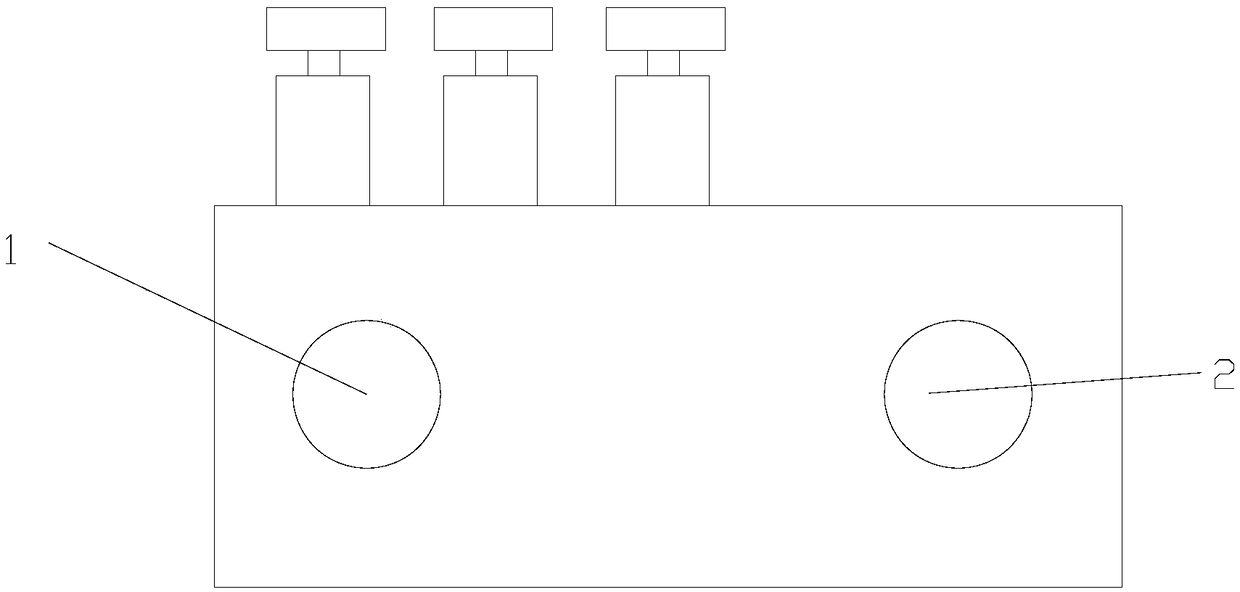
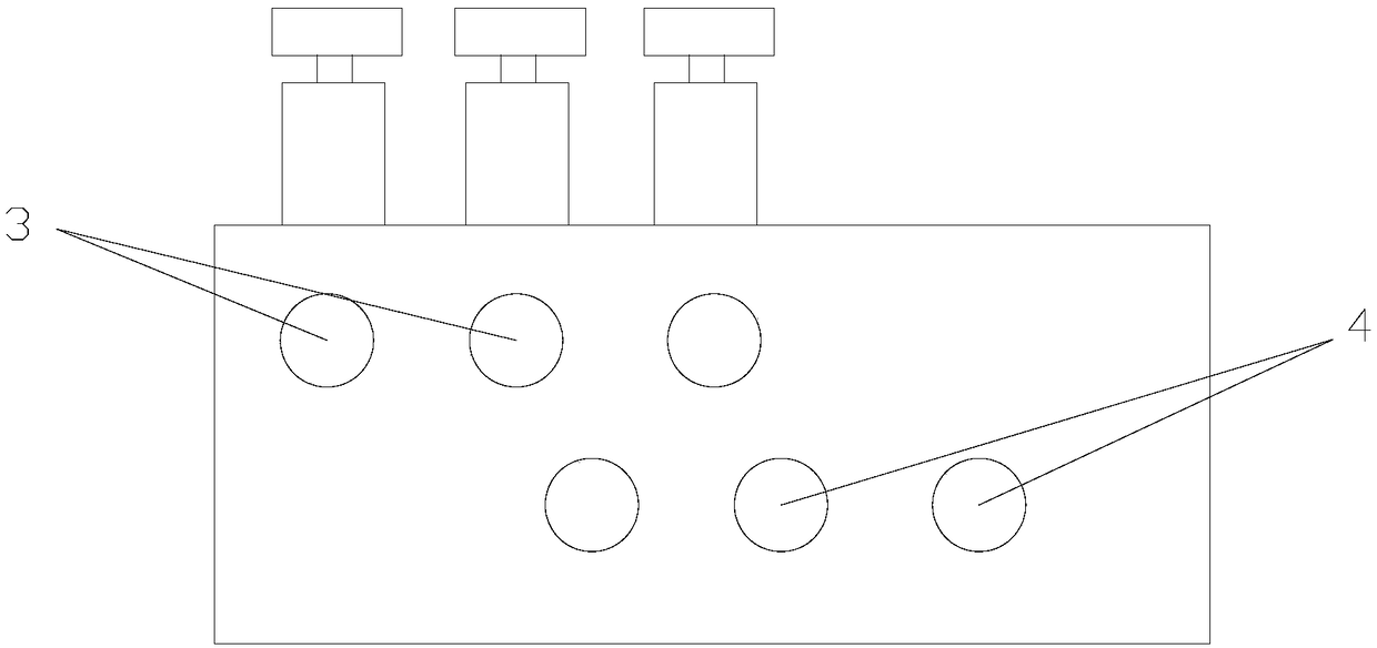
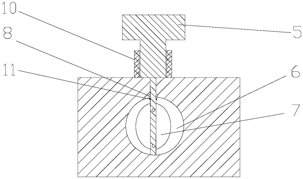
[0015] figure 1 It is a structural schematic diagram of the present invention, figure 2 for figure 1 back view of the image 3 It is a structural schematic diagram of the speed regulating mechanism in the present invention. As shown in the figure, the integrated speed regulating hydraulic valve group in this embodiment includes a valve block, and the valve block is provided with a main oil inlet port 1 and a main oil return port 2 , a plurality of diversion outlets 3 and a plurality of diversion inlets 4, the total oil inlet communicates with a plurality of diversion outlets through a diversion passage arranged inside the valve block, and the total oil return port communicates with a plurality of diversion outlets through a confluence passage arranged inside the valve block It is connected with a plurality of diversion inlets, and also includes a speed regulating mechanism for independently adjusting the flow rate of the liquid in each diversion outlet; the number of the di...


PUM


Abstract

The invention discloses an integrated speed-regulating hydraulic valve group. The integrated speed-regulating hydraulic valve group comprises a valve block, and further comprises a speed regulating mechanism, wherein a main oil inlet, a main oil return hole, a plurality of flow-dividing outlets and a plurality of flow-dividing inlets are formed in the valve block; the main oil inlet communicates with the flow-dividing outlets through a flow-dividing channel arranged inside the valve block; the main oil return hole communicates with the flow-dividing inlets through a confluence channel arrangedinside the valve block; the speed regulating mechanism is used for independently regulating flow speed of liquid in each flow-dividing outlet; and through the speed regulating mechanism which is usedfor used for independently regulating flow speed of liquid in each flow-dividing outlet, control over ejecting-out speed and punching speed in a hydraulic forming press can be realized, so that the problems such as ejecting deviation or hole collapse caused by too great speed difference of the flow-dividing channel are avoided.

Description

technical field [0001] The invention relates to the field of valve control, in particular to an integrated speed-regulating hydraulic valve group. Background technique [0002] The existing integrated speed-regulating hydraulic valve group uses the branch channel and the confluence channel to realize the branching of the hydraulic oil, and the flow rate of each oil channel is equal, and the difference of the oil inlet speed is uncontrollable, which is not conducive to the hydraulic forming press. It is pointed out that the control of punching speed will cause problems such as top deviation and hole collapse caused by excessive speed difference. [0003] Therefore, in order to solve the above problems, an integrated speed-regulating hydraulic valve group is needed, which can control the ejection and punching speed in the hydroforming press, and avoid problems such as top deviation and hole collapse caused by excessive speed differences in the runners. . Contents of the inv...

Claims


Application Information

Patent Timeline
Patent Type & Authority Applications(China)
IPC IPC(8): F15B13/02
CPCF15B13/022
Inventor 朱云翼万光毅王崇茂李明亮王勇黎泰丞
Owner 重庆宝钢汽车钢材部件有限公司
Why Eureka
Try Eureka