Electromechanical equipment fixing device and using method thereof

A technology of electromechanical equipment and fixing devices, which is applied in the direction of mechanical equipment, electrical equipment structural parts, clamping/extracting devices, etc., can solve problems such as simple structure, poor shockproof performance, and easy shaking, so as to reduce the damage of the main body of electromechanical equipment , Maximize the vibration reduction effect, and achieve the effect of adjustability

Inactive Publication Date: 2018-11-02
武汉朋鼎科技有限公司
View PDF3 Cites 10 Cited by
  • Summary
  • Abstract
  • Description
  • Claims
  • Application Information

AI Technical Summary

Problems solved by technology

[0002] Electromechanical equipment generally refers to machinery, electrical appliances and electrical automation equipment, which can be divided into three categories according to their uses, namely industrial electromechanical equipment, information electromechanical equipment and livelihood electromechanical equipment. It is easy to shake under the ground. The existing electromechanical equipment fixing method generally uses bolts to fasten the equipment body and the ground surface. When the equipment rotates at high speed, the vibration will easily loosen the bolts and the stability is poor. In addition, the existing electromechanical equipment has a simple structure and good shockproof performance. Poor, electromechanical equipment produces strong vibration during use, which may easily cause damage to electromechanical equipment

Method used


Image

  • Electromechanical equipment fixing device and using method thereof
  • Electromechanical equipment fixing device and using method thereof
  • Electromechanical equipment fixing device and using method thereof

Examples


Embodiment Construction

[0025] The technical solutions in the embodiments of the present invention will be clearly and completely described below with reference to the accompanying drawings in the embodiments of the present invention. Obviously, the described embodiments are only a part of the embodiments of the present invention, but not all of the embodiments. Based on the embodiments of the present invention, all other embodiments obtained by those of ordinary skill in the art without creative efforts shall fall within the protection scope of the present invention.

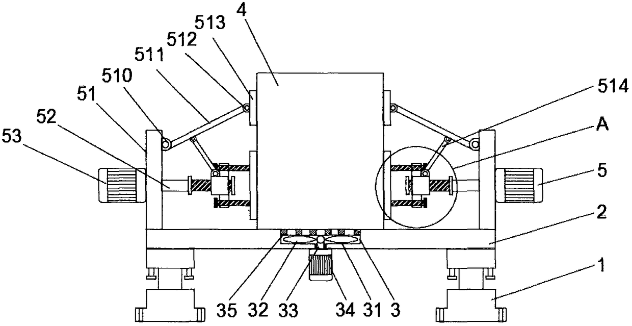
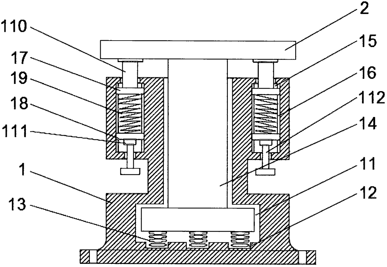
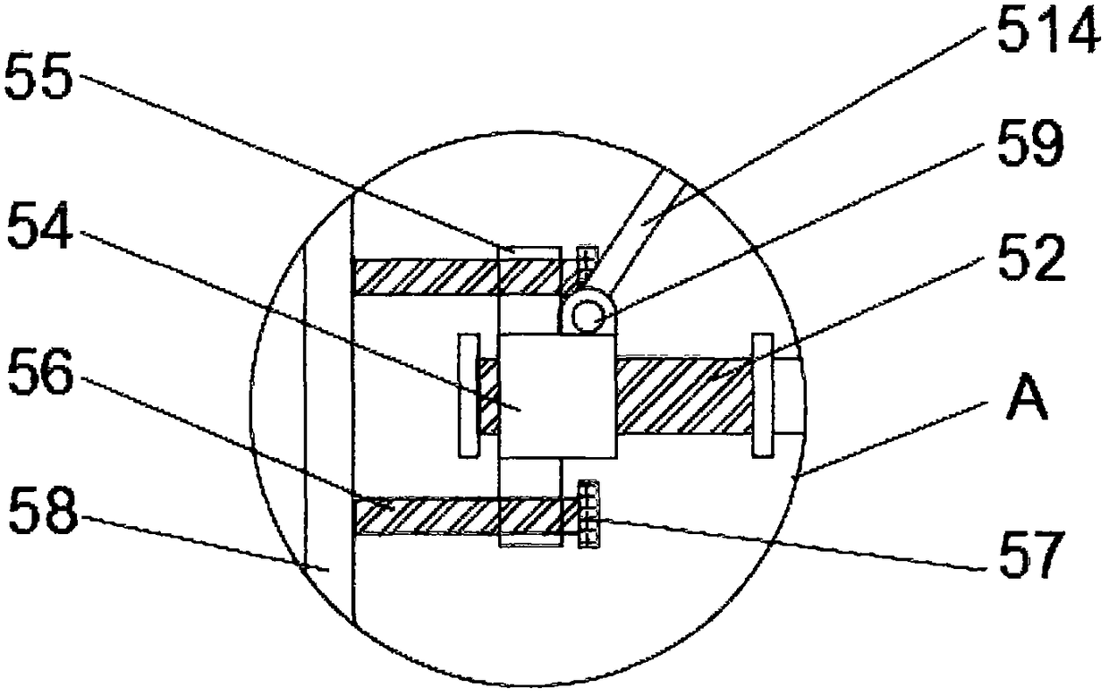
[0026] see Figure 1-3 The present invention provides a fixing device for electromechanical equipment, comprising a vibration damping base 1, a fixing plate 2, a heat sink 3, a main body of electromechanical equipment 4 and a clamping device 5, the upper end of the vibration damping base 1 is provided with a fixing plate 2, and the lower end of the fixing plate 2 A heat dissipation device 3 is arranged in the middle part, an electrome...


PUM


Abstract

The invention discloses an electromechanical equipment fixing device and a using method thereof. A vibration damping base comprises a T-shaped hole, grooves, wavy springs, a T-shaped column, a vibration damping cavity, sliding rails, first sliding blocks, second sliding blocks, vibration damping springs, buffer rods, first shaft seats and adjusting screws; the T-shaped hole is formed in the middlepart of the upper end of the vibration damping base; the grooves are uniformly formed in the lower end of the T-shaped hole; the wavy springs are arranged in the grooves; the T-shaped column is arranged at the parts, corresponding to the interior of the T-shaped hole, of the upper ends of the wave springs; vibration damping cavities are formed in the parts, corresponding to the two sides of the T-shaped hole, of the upper end of the vibration damping base; and the sliding rails are arranged at the inner side walls of the vibration damping cavities. With the adoption of the electromechanical equipment fixing device, a main body of electromechanical equipment is radiated advantageously; the main body of the electromechanical equipment is prevented from loosening advantageously and the stability of the electromechanical equipment fixing device is further strengthened; and a vibration damping function is played advantageously, thereby maximizing the vibration damping effect of the whole vibration damping base and reducing the probability of damage to the main body of the electromechanical equipment caused by vibration.

Description

technical field [0001] The invention relates to the technical field of electromechanical equipment, in particular to a fixing device for electromechanical equipment and a method for using the same. Background technique [0002] Electromechanical equipment generally refers to machinery, electrical appliances and electrical automation equipment, which can be divided into three categories according to their uses, namely industrial electromechanical equipment, information electromechanical equipment and people's livelihood electromechanical equipment. The existing electromechanical equipment is usually fastened to the ground by bolts. The vibration generated when the equipment rotates at a high speed is easy to loosen the bolts, and the stability is poor. In addition, the existing electromechanical equipment has a simple structure and is resistant to shocks. Poor, the electromechanical equipment produces strong vibration during use, which is easy to cause damage to the electrome...

Claims


Application Information

Patent Timeline
Patent Type & Authority Applications(China)
IPC IPC(8): F16M5/00F16M7/00F16F7/00H05K7/14H05K7/20
CPCF16M5/00F16F7/00F16M7/00H05K7/1401H05K7/20136
Inventor 周斌张成国苗晓辉郑晗
Owner 武汉朋鼎科技有限公司
Why Eureka
Try Eureka