Electronic teaching test box

An electronic teaching and test box technology, applied in teaching models, electrical equipment casings/cabinets/drawers, electrical components, etc., can solve the problems of inconvenient handling of electronic components, damage to test box components, and inability to carry complete experiments. Achieve the effect of ensuring normal working environment, facilitating parallel connection and simple structure

Inactive Publication Date: 2018-11-02
黄永怀
View PDF8 Cites 1 Cited by
  • Summary
  • Abstract
  • Description
  • Claims
  • Application Information

AI Technical Summary

Problems solved by technology

However, the existing test boxes for electronic information teaching have the problem that it is inconvenient to take and place electronic components, and the electronic components are easy to lose. Most of the current experimental equipment is scattered, and there are many equipment that need to be carried when doing experiments, often due to negligence. The experiment cannot be carried out as scheduled, which brings inconvenience to the experiment, and the storage of the existing power cord is more troublesome.
The current large-scale experimental teaching needs to be carried out continuously for several hours. The temperature generated by the components in summer will bring greater working pressure to the electronic test box. to cause greater damage, so we need an electronic teaching test box with functions such as heat dissipation and drop resistance

Method used


Image

  • Electronic teaching test box
  • Electronic teaching test box
  • Electronic teaching test box

Examples


Embodiment Construction

[0016] The following will clearly and completely describe the technical solutions in the embodiments of the present invention with reference to the accompanying drawings in the embodiments of the present invention. Obviously, the described embodiments are only some, not all, embodiments of the present invention. Based on the embodiments of the present invention, all other embodiments obtained by persons of ordinary skill in the art without making creative efforts belong to the protection scope of the present invention.

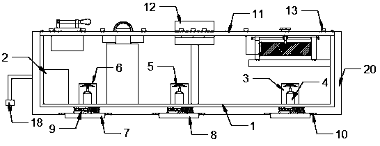
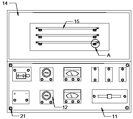
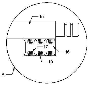
[0017] see Figure 1-3 , the present invention provides a technical solution: an electronic teaching test box, including a box body 1, a transformer 2 is fixedly installed on one side of the box body 1, and a plurality of heat dissipation devices are fixedly installed on the side close to the transformer 2 of the box body 1 Mechanism 3. The heat dissipation mechanism 3 includes a motor 4, a fan blade 5, and a heat dissipation net 6. The side of the heat dissip...


PUM


Abstract

The invention discloses an electronic teaching test box which comprises a housing. One inner side of the housing is provided with a transformer which is fixedly arranged. A plurality of heat radiatingmechanisms are fixedly arranged at one side, which is next to the transformer, of the housing. The heat radiating mechanism comprises a motor, blades and a heat radiating net. A motor is fixedly arranged through a mounting seat on one side, which is next to the housing, of the heat radiating mechanism. A blade shaft is fixedly arranged at the output end of the motor. The heat radiating mechanismis movably mounted at one side, which is far from the motor, of the blade. A buffering mechanism is movably mounted at one side, which is far from the heat radiating mechanism, of the housing. The buffering mechanism comprises a buffering plate, a first spring and a fixed plate. The first spring is movably mounted at one side, which is next to the housing, of the buffering mechanism. The electronic teaching test box has advantages of realizing experiment teaching to the students, facilitating quick cross-slubbing connection, keeping a stable working state of an experiment box, and further improving experiment effect. The electronic teaching test box has advantages of simple structure, high convenience in use, and high use effect.

Description

technical field [0001] The invention relates to the academic field of electronic teaching, in particular to an electronic teaching test box. Background technique [0002] In the teaching process of electronic circuits, in order to facilitate students' learning and understanding, a large number of circuit experiments are often used to assist teaching. However, the existing test box is mainly composed of a box body, a box cover and a circuit board. The circuit board It is fixed in the box, and a certain space for storing components and connecting lines is reserved in the box. When in use, the box is placed horizontally on the table. Modern communication technology is set for students majoring in electronics and communication engineering. There are many teaching contents. For teachers to complete the teaching of communication principles and other related knowledge through lecturing, the realization rate of students filtering the teacher's language into their own knowledge reser...

Claims


Application Information

Patent Timeline
Patent Type & Authority Applications(China)
IPC IPC(8): G09B23/18H05K7/20H05K7/02H05K5/02
CPCG09B23/185H05K5/0217H05K5/0247H05K7/02H05K7/20172
Inventor 黄永怀
Owner 黄永怀
Why Eureka
Try Eureka