
Multi-focus child glasses processing device

A processing device and multi-focus technology, which is applied in the direction of grinding drive device, metal processing equipment, lens, etc., can solve the problems of easy wear of the lens, large difference in clamping strength, and affecting the efficiency of grinding, so as not to slip off and improve Convenience, the effect of reducing the chance of falling

Active Publication Date: 2021-03-09
NANJING LINGQUE INTELLIGENT MFG CO LTD
View PDF6 Cites 0 Cited by
  • Summary
  • Abstract
  • Description
  • Claims
  • Application Information

AI Technical Summary

Problems solved by technology

[0003] The existing glasses processing device needs to clamp the middle part of the lens when grinding the lens. Since the thickness of the normal lens gradually increases or decreases from the center to the edge, when clamping the lens, the design The clamping block is convex or concave to realize the clamping of the lens, but due to the characteristics of the multi-focal lens itself, the thickness of the middle gradient area will become thicker towards the bottom, which will cause the middle gradient of the multi-focal lens during clamping There is a large difference in the clamping strength of the thin area, the clamping strength of the thinner part is small, and the clamping strength of the thicker part is greater, which will cause the lens in the thicker part to be easily worn and affect the quality after processing. It is necessary to use specific auxiliary accessories to absorb the lens before holding, and then put the auxiliary accessories horizontally on the grinding position to prevent the lens from falling when the clamping part is opened after grinding. After removal, the auxiliary accessories need to be removed from the lens. Remove it, increase the process and affect the efficiency of grinding

Method used


Image

  • Multi-focus child glasses processing device
  • Multi-focus child glasses processing device
  • Multi-focus child glasses processing device

Examples


Embodiment approach

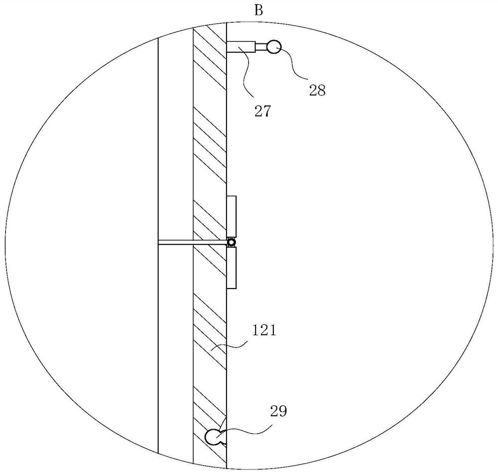
[0033] As a specific embodiment of the present invention, the limit card slot 121 includes a plurality of sub-slots 18, a hinge is arranged between two adjacent sub-slots 18, and the plurality of sub-slots 18 are in sequential contact with each other in the vertical direction. , and the bottom of the slot 18 is provided with a horizontal slot 19 and a vertical slot 20, the horizontal slot 19 communicates with the vertical slot 20, one end of the horizontal slot 19 is located on the inner side of the slot 18, and the bottom end of the vertical slot 20 is located at the bottom of the slot 18 On the bottom groove wall, a horizontal plate 21 is provided in the horizontal groove 19, and a vertical plate 22 is inserted on the horizontal plate 21. The vertical plate 22 is positioned in the vertical groove 20, and the top of the horizontal plate 21 is provided with a triangular groove 23, and The inside of the straight plate 22 is provided with a triangular plate 24, one end of the hor...


PUM


Abstract

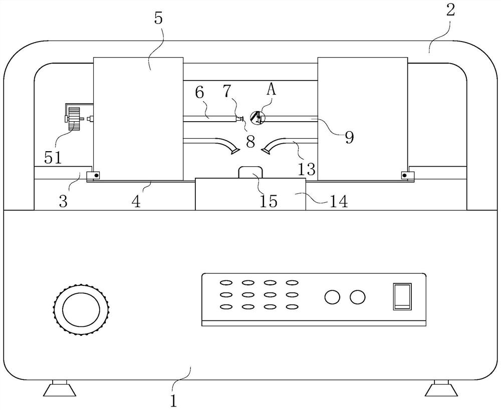
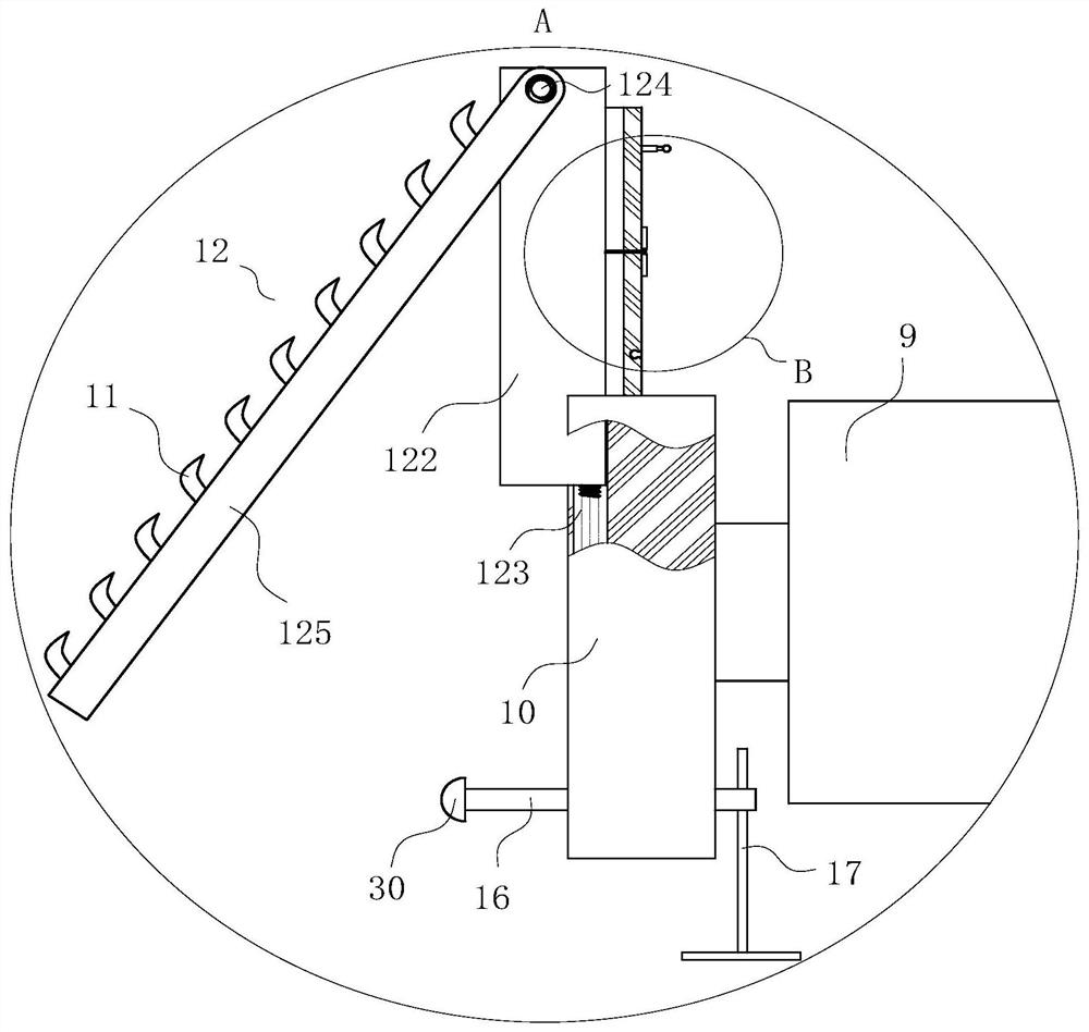
The invention discloses a multi-focus child glasses processing device. The processing device comprises a machine body; a mounting cover is fixedly connected to the top of the machine body; an openingis formed in the front side of the mounting cover; a deflection motor is mounted on the inner side of the mounting cover; a deflection frame is fixedly connected to the output end of the deflection motor; and power boxes are fixedly connected to the two sides of the top of the deflection frame. According to the processing device, the inner side of a lens is obliquely attached to an attaching plate, when the lens is vertical, the approximately-vertical attaching plate can make contact with the part of the gradual change area, a rubber pad is prone to deformation and has the best supporting effect for the lens, it is guaranteed that the clamping strength difference of all positions is not too large, when an abutting disc is disengaged from the lens after polishing is completed, a torsion spring drives the attaching plate to rotate, finally, the attaching plate rotates from an approximately-vertical state to an inclined state, and under the action of the rubber pad on the surface of the attaching plate, the polished lens is finally kept stable and not prone to sliding-off, and the falling probability of the lens is reduced.

Description

technical field [0001] The invention belongs to the technical field of glasses production, and in particular relates to a multi-focus children's glasses processing device. Background technique [0002] Progressive multifocal lenses refer to lenses with continuous and uninterrupted gradual changes in luminosity from far to near. The main feature of Progressive Additional Lens is that there is a transition zone where the refractive power continuously changes between the fixed far vision zone above the lens and the fixed near vision zone below the lens. This lens zone is called the gradient zone. In this area, the refractive power (degree) of the lens increases gradually through the gradual reduction of the radius of curvature of the lens, thereby providing the wearer with full and continuous clear vision from the far point to the near point. [0003] The existing glasses processing device needs to clamp the middle part of the lens when grinding the lens. Since the thickness o...

Claims


Application Information

Patent Timeline
Patent Type & Authority Applications(China)
IPC IPC(8): B24B13/00B24B13/005B24B13/06B24B47/00
CPCB24B13/0012B24B13/005B24B47/00B24B13/06
Inventor 黄文强
Owner NANJING LINGQUE INTELLIGENT MFG CO LTD
Learn More