Solar cell, solar cell string and lamination tile photovoltaic module

A technology for solar cells and photovoltaic modules, applied in photovoltaic power generation, electrical components, circuits, etc., can solve problems such as the reduction of output power of shingled photovoltaic modules, and achieve the effect of avoiding hot spot effects and saving costs.

Inactive Publication Date: 2018-11-02
YINGLI ENERGY CHINA
View PDF10 Cites 7 Cited by
  • Summary
  • Abstract
  • Description
  • Claims
  • Application Information

AI Technical Summary

Problems solved by technology

[0003] In view of this, the embodiment of the present invention provides a solar cell, a solar cell string and a shingled photovoltaic module to solve the problem that when the solar cells in the shingled module in the prior art are shaded, the bypass diode will shield the entire battery string, As a result, the output power of shingled photovoltaic modules is significantly reduced

Method used


Image

  • Solar cell, solar cell string and lamination tile photovoltaic module
  • Solar cell, solar cell string and lamination tile photovoltaic module
  • Solar cell, solar cell string and lamination tile photovoltaic module

Examples


Embodiment 1

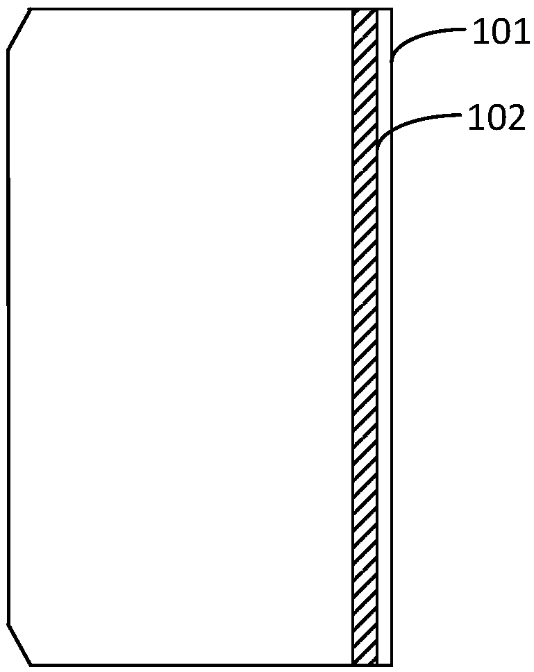
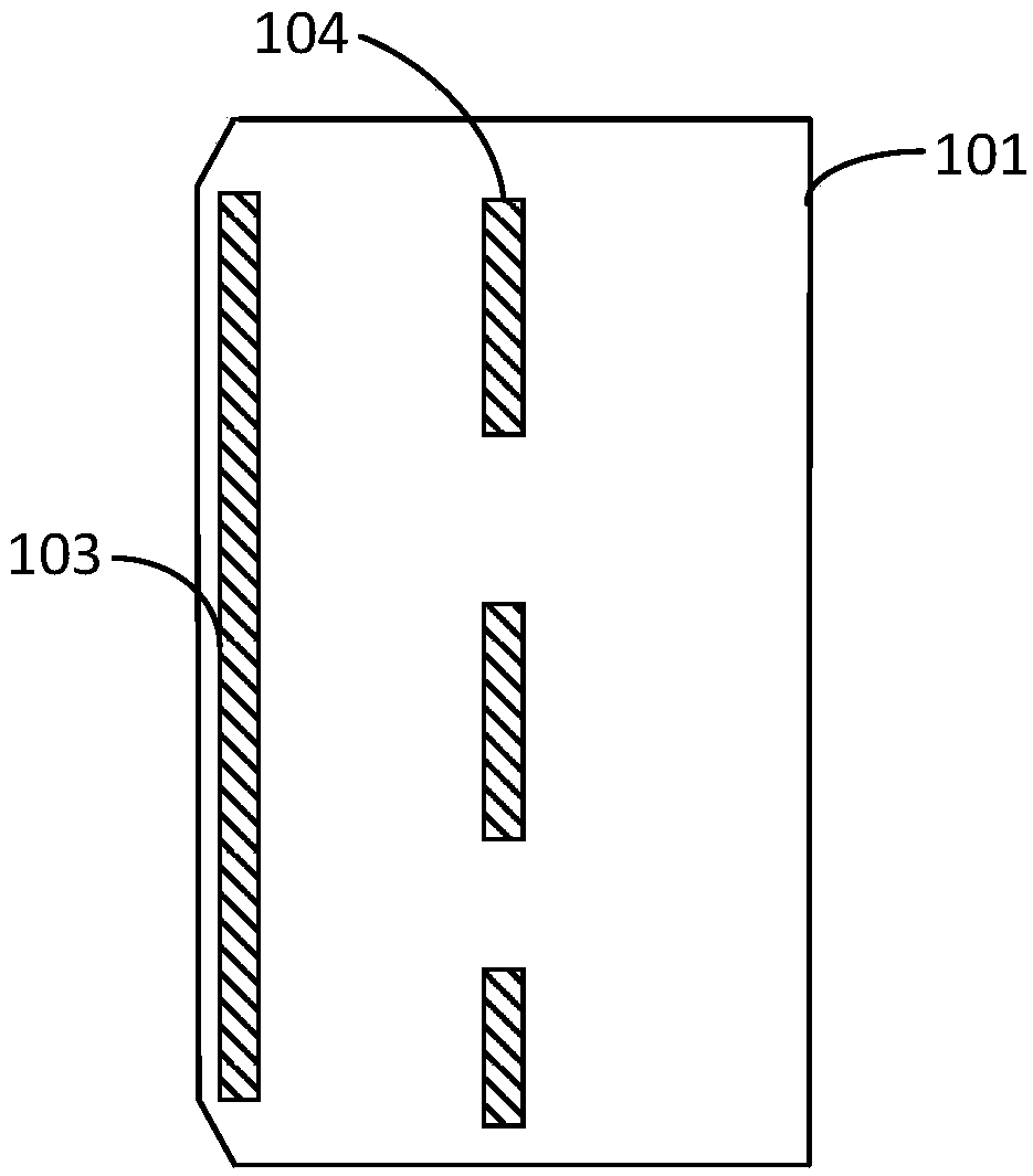
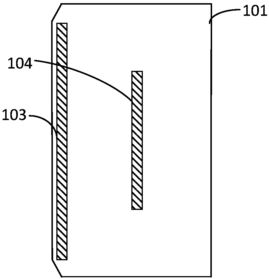
[0025] Please refer to Figure 1 to Figure 3 , the front side of the solar cell 101 is provided with a front busbar 102, and the back side of the solar cell 101 is provided with a back busbar 103, and the front side busbar 102 and the back side busbar 103 are respectively located in the solar cell 101 on both sides. The back side of the solar cell 101 is further provided with an auxiliary grid line 104 parallel to the rear main grid line 103 .

[0026] In this embodiment, the front busbar 102 is provided on the front side of the solar cell 101 , and the back busbar 103 is provided on the back side. The distance between the front busbar 102 and one edge of the solar cell 101 is less than or equal to 1 mm, and the distance between the back busbar 103 and the other edge of the solar cell 101 is less than or equal to 1 mm. The front side of the solar cell 101 is also provided with front fine grid lines (not shown in the drawings), and the back side is also provided with rear fin...

Embodiment 2

[0032] Please refer to Figure 4 to Figure 5 , a solar cell string, including: a plurality of solar cells 101 according to Embodiment 1 of the present invention, and the solar cells 101 are connected in a shingled shape, wherein, the front busbar 102 of any solar cell 101 and its adjacent The rear busbars 103 of the solar cells 101 are overlapped.

[0033] The back of the solar cells in the solar cell string in this embodiment is provided with additional grid lines 104. When the solar cell strings are connected into shingled photovoltaic modules, the current can bypass the solar cells through the additional grid lines 104 to avoid hot spots. Effect, will not lead to the failure of the entire battery string, so that the output power of the photovoltaic module will not be significantly reduced, and there is no need to connect bypass diodes, which can save costs.

[0034] Please refer to Figure 6 , Shingled photovoltaic module, including: a plurality of solar cells as describe...


PUM


Abstract

The invention is applicable to the technical field of photovoltaic power generation and provides a solar cell, a solar cell string and a lamination tile photovoltaic module. The lamination tile photovoltaic module comprises a plurality of solar cells, wherein accessory grid lines are arranged on back surfaces of the solar cells, the solar cells are connected in a lamination tile shape to form sub-cell strings, a front-surface main grid line of an arbitrary solar cell is in overlap joint with a back-surface main grid line of the adjacent solar cell, a plurality of sub-cell strings arranged in parallel are connected in parallel to form the cell string by a first parallel convergence strip and a second parallel convergence strip, the corresponding accessory grid lines in the plurality of sub-cell strings arranged in parallel are connected by conductive strips, and the plurality of cell strings arranged in parallel are connected in series by series convergence strips. When a solar cell piece is shielded, a current can pass by the shielded solar cell by the accessory grid lines, and a hot spot effect is prevented.

Description

technical field [0001] The invention belongs to the technical field of photovoltaic power generation, and in particular relates to a solar cell, a solar cell string and a shingled photovoltaic module. Background technique [0002] Shingled photovoltaic modules cut solar cells into small cells, connect the small cells in the form of shingles to form battery strings, and then connect the battery strings in parallel or in series to form shingled photovoltaic modules. In order to prevent the cells in the shingled photovoltaic module from being shaded to cause hot spot effect, a bypass diode is usually connected in the shingled module, and the bypass diode is connected between two parallel battery strings. When there is a cell in the battery string When shaded, the bypass diodes will shield the entire battery string, resulting in a significant reduction in the output power of the shingled PV module. Contents of the invention [0003] In view of this, the embodiment of the pres...

Claims


Application Information

Patent Timeline
Patent Type & Authority Applications(China)
IPC IPC(8): H01L31/0224H01L31/05
CPCH01L31/022433H01L31/0504Y02E10/50
Inventor 冯天顺张向前刘凤柳刘妍张丽娜刘凯辉刘彩凤
Owner YINGLI ENERGY CHINA
Why Eureka
Try Eureka