Antenna control method and terminal equipment

A technology of terminal equipment and antenna modules, which is applied in the direction of antennas, antenna arrays, antenna components, etc., and can solve problems such as strong radiation

Inactive Publication Date: 2018-11-02
VIVO MOBILE COMM CO LTD
View PDF6 Cites 15 Cited by
  • Summary
  • Abstract
  • Description
  • Claims
  • Application Information

AI Technical Summary

Problems solved by technology

[0004] Embodiments of the present invention provide an antenna control method and a terminal device to solve the problem of strong radiation from the antenna structure of the terminal device to the human body in the prior art

Method used


Image

  • Antenna control method and terminal equipment
  • Antenna control method and terminal equipment
  • Antenna control method and terminal equipment

Examples


Embodiment Construction

[0023] The following will clearly and completely describe the technical solutions in the embodiments of the present invention with reference to the accompanying drawings in the embodiments of the present invention. Obviously, the described embodiments are some of the embodiments of the present invention, but not all of them. Based on the embodiments of the present invention, all other embodiments obtained by persons of ordinary skill in the art without creative efforts fall within the protection scope of the present invention.

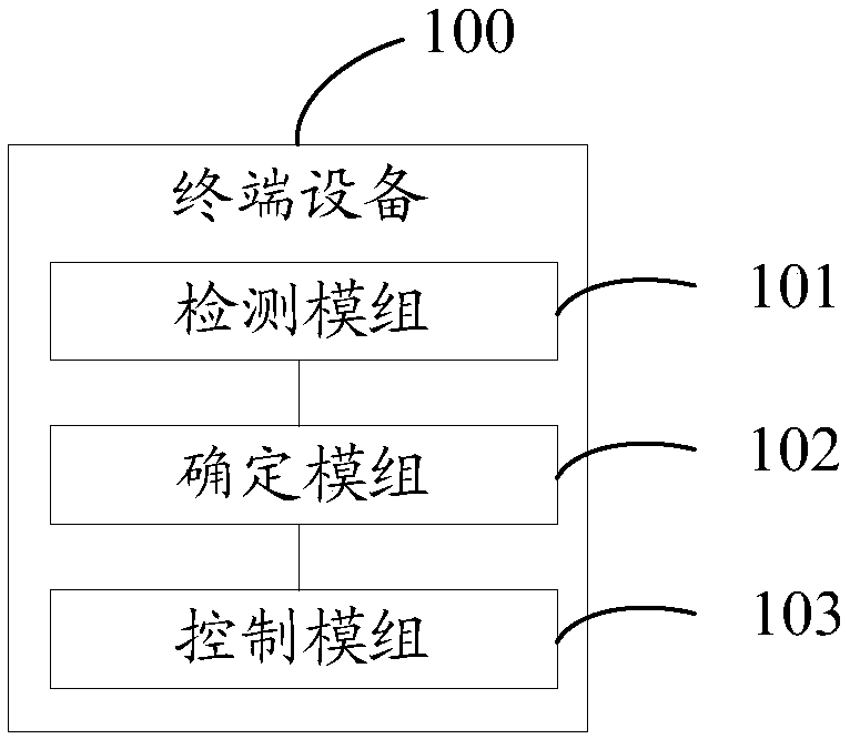
[0024] Such as figure 1 As shown, the embodiment of the present invention provides a terminal device 100, including:

[0025] a first antenna module (not shown) having a radiator;

[0026] A second antenna module (not shown) having a radiator;

[0027] The detection module 101 is used to detect the target part of the human body, and obtain a detection result capable of indicating the position information of the target part of the human body;

[0028...


PUM


Abstract

The invention provides an antenna control method and terminal equipment. The terminal equipment comprises a first antenna module, a second antenna module, a detection module, a determination module and a control module, wherein the first antenna module is provided with a radiation body, the second antenna module is provided with a radiation body, the detection module is used for detecting a humanbody target part and obtaining a detection result capable of indicating position information of the human body target part, the determination module is used for determining a target antenna module according to the detection result obtained by the detection module, the target antenna module is the antenna module of which the radiation body in the first antenna module and the second antenna module is farther away from the human body target part, and the control module is used for controlling the target antenna module determined by the determination module to be in a working state and the other antenna module except the target antenna module to be in a closed state. Therefore, the radiation influence of the antenna module in the working state on the human body target part can be reduced, anda human body specific absorption rate (SAR) value during the working process of the antenna module is reduced.

Description

technical field [0001] The present invention relates to the field of communication technology, in particular to an antenna control method and terminal equipment. Background technique [0002] The antenna structure of the terminal equipment is generally arranged on the casing of the terminal equipment, and is distributed on the upper and lower sides of the casing, so as to realize the communication function of the terminal equipment. For example, in the process of telephone communication, the antenna located on the lower side of the casing is held by the user, resulting in poor performance of the lower antenna, and at this time, the communication function of the terminal device is mainly realized by the upper antenna; During the process, the terminal device is close to the ear, and the upper antenna is also close to the ear, so that the SAR (Specific Absorption Rate) value of the human body is high, especially the SAR value at the ear is high, which endangers human safety. ...

Claims


Application Information

Patent Timeline
Patent Type & Authority Applications(China)
IPC IPC(8): H01Q1/24H01Q1/50H01Q21/00
CPCH01Q1/245H01Q1/50H01Q21/00H01Q21/0006
Inventor 李东明
Owner VIVO MOBILE COMM CO LTD
Why Eureka
Try Eureka