
Pump impeller having separated offset inlet venes

A blade and impeller technology, applied in the field of single-stage end-suction centrifugal pumps, can solve problems such as highly unstable liquid flow, pressure head and efficiency decay, pressure pulse, etc.

Inactive Publication Date: 2002-07-10
FLOWSERVE MANAGEMENT CO
View PDF3 Cites 0 Cited by
  • Summary
  • Abstract
  • Description
  • Claims
  • Application Information

AI Technical Summary

Problems solved by technology

Thus, the potential for undesirable cavitation is increased, which causes several side effects, namely: a) a significant drop in head and efficiency of the pump, unless by greatly increasing the feed tank (which increases the cost of tank installation) or High suction pressure is provided by reducing the pump motor speed; b) due to the large volume of water vapor in the pump will cause pressure pulses, subjecting the pump to highly unstable liquid flow, even surge, thus reducing pump reliability and increasing Repair costs; c) due to cavitation, the impeller is quickly damaged along with other pump components such as wear rings, suction vanes, volute tongues or diffuser vanes

Method used


Image

  • Pump impeller having separated offset inlet venes
  • Pump impeller having separated offset inlet venes
  • Pump impeller having separated offset inlet venes

Examples


Embodiment Construction

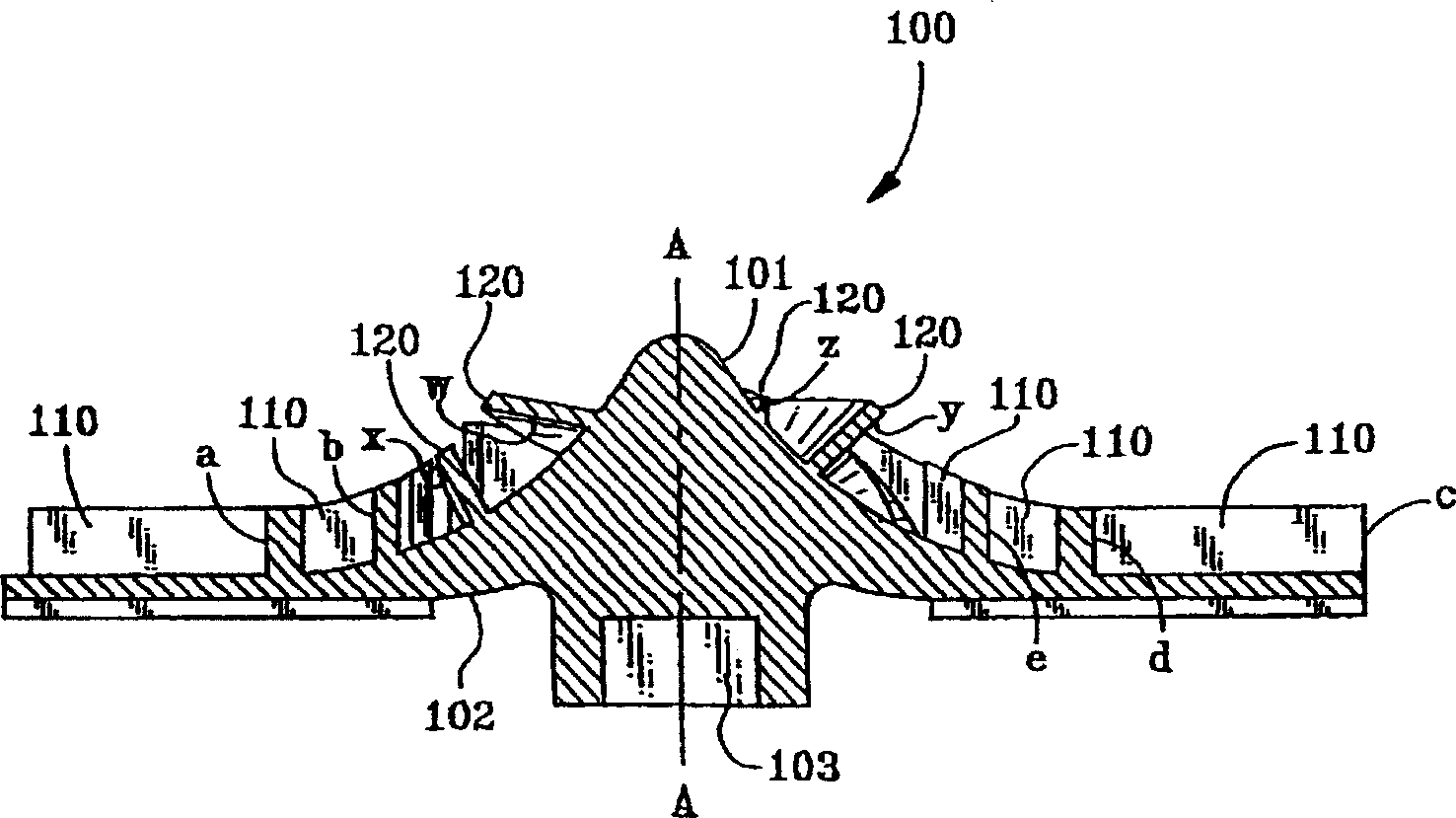
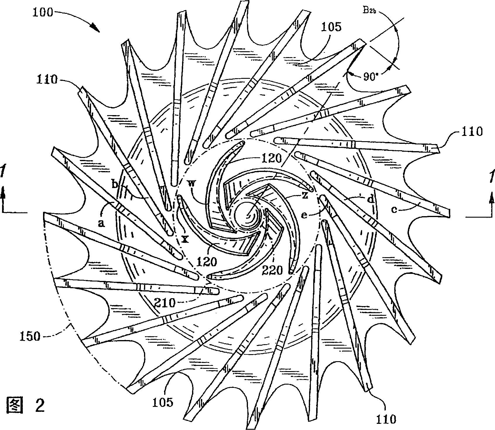
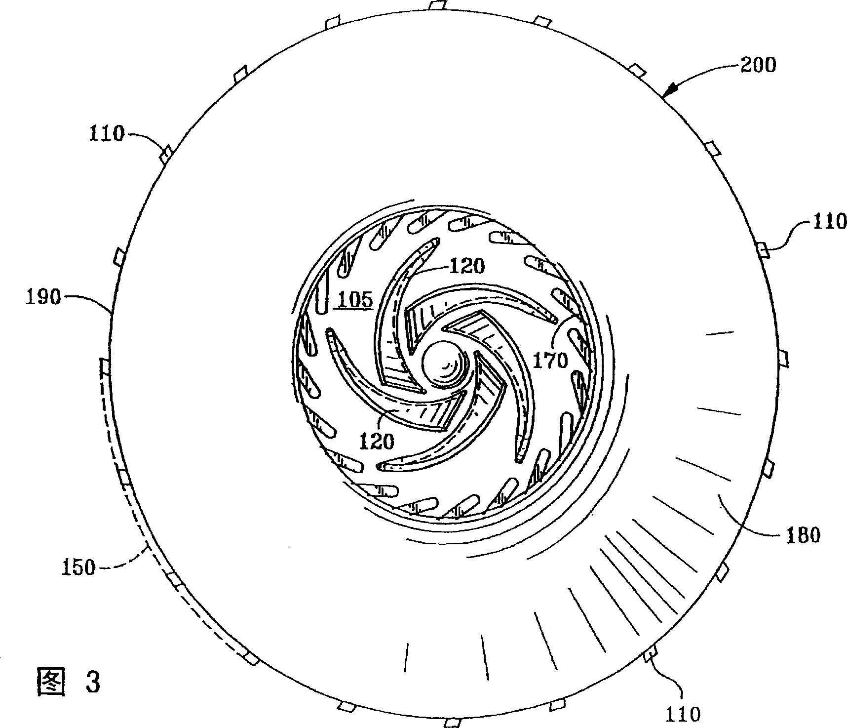
[0015] The design issues described above are resolved by using separate offset rows of twisted blades at the impeller inlet while maintaining the multiple blade principle at the outlet to create a higher discharge head coefficient. In this way, the vane inlet angle is optimized and occlusion of the inlet is reduced by selecting fewer inlet vanes. The resulting pump has an increased ability to operate at low suction pressures while maintaining the high discharge head capability of the pump. A preferred embodiment of the present invention is explained in more detail below with reference to the accompanying drawings. The drawing of the impeller does not include the pump casing with its base, inlet and discharge ports and rotating drive mechanism. These are standard designs and not part of the claimed invention.

[0016] figure 1 and 2 are schematic illustrations of an open impeller 100 showing, respectively, a cross-sectional view (in the direction of arrow 1-1 in FIG. 2 ) and...


PUM


Abstract

A fluid impeller (100) for a centrifugal pump includes a hub (105) having a substantially disk-like form with a center and an edge, circular symmetry, and provosion for being rotatably driven. A first plurality of pumping vanes (110) projects substantially perpendicularly from a first surface of the hub and extends radially outwardly from a locus (210) near the center of the hub to another locus (150) near the edge of the hub. These vanes (110) provide a high pressure head with a small impeller diameter. A second plurality of separate and twisted inlet vanes (120) also projects substantially perpendicularly from the first surface of the hub and extends radially outwardly to the locus (210) near the center of the hub from another locus (220) nearer the center of the hub. The separate second plurality of vanes (120), by turning and pre-pressurizing the fluid, provides an impeller having capability of cavitation-free pumping at low net positive suction head (NPSH). A front shroud (180) can be used which partially or totally covers the first and / or second plurality of vanes.

Description

Background of the invention [0001] This invention relates generally to single stage end suction centrifugal pumps and more particularly to centrifugal pumps having both open and shrouded impellers for low flow, high head applications. [0002] Centrifugal end suction pumps are well known and widely used. There are many different types of such pumps, but few are specifically designed for low flow applications requiring high head pressure, while having high efficiency, good suction performance, and high suction reliability (or low maintenance). In most cases, low flow rate operation will be accommodated with a pump that is oversized for the flow required by the intended application. This provides the required pumping capacity, but it also means that the pump has to operate at off-design conditions, which not only wastes energy, but also increases the likelihood of damage due to highly unstable hydraulic loads caused by internal fluid separation . In addition, since a high hea...

Claims


Application Information

Patent Timeline
Patent Type & Authority Patents(China)
IPC IPC(8): F04D29/22F04D29/24
CPCF04D29/2277F04D29/242
Inventor A·帕顿B·施尔维罗G·里加蒙蒂
Owner FLOWSERVE MANAGEMENT CO
Learn More