X-ray machine and recumbent-position imaging correction method implemented by same

A calibration method and X-ray machine technology, applied in the field of X-ray machines, can solve the problems of cumbersome alignment process and low efficiency, and achieve the effect of high efficiency and convenient and simple calibration process

Active Publication Date: 2018-11-06
SHANGHAI UNITED IMAGING HEALTHCARE
View PDF11 Cites 4 Cited by
  • Summary
  • Abstract
  • Description
  • Claims
  • Application Information

AI Technical Summary

Problems solved by technology

[0003] However, for shooting in the supine position, the bed board of the imaging bed needs to be moved to one side, and then t

Method used


Image

  • X-ray machine and recumbent-position imaging correction method implemented by same
  • X-ray machine and recumbent-position imaging correction method implemented by same
  • X-ray machine and recumbent-position imaging correction method implemented by same

Examples


Embodiment Construction

[0020] In order to make the object, technical solution and advantages of the present invention clearer, the present invention will be further described in detail below in conjunction with the accompanying drawings and embodiments. It should be understood that the specific embodiments described here are only used to explain the present invention, not to limit the present invention.

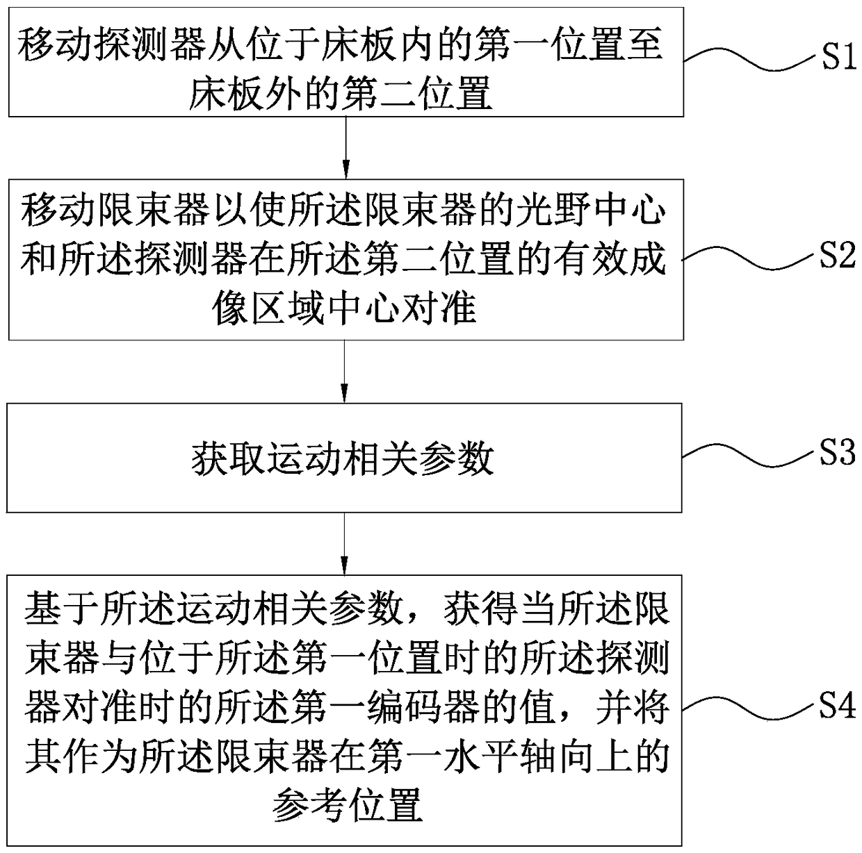
[0021] See figure 1 , the present invention provides a method for correcting horizontal position imaging of an X-ray machine, which is used for correcting a beam limiter and a detector in an X-ray machine, comprising the following steps:

[0022] Step S1: Moving the detector along the first horizontal axis in the three-dimensional coordinate system from a first position inside the bed board to a second position outside the bed board. When the detector is located outside the bed board, it is necessary to ensure that the bed board does not block the center of the effective imaging area of ​​the dete...


PUM


Abstract

The invention relates to a recumbent-position imaging correction method implemented by an X-ray machine. The recumbent-position imaging correction method includes steps of shifting a detector from a first location in a bed board to a second location outside the bed board along a first horizontal axial direction in a three-dimensional coordinate system; shifting a beam limiting device to align thecenter of a light field of the beam limiting device with the center of an effective imaging region of the detector at the second location; acquiring movement related parameters; acquiring values of afirst encoder on the basis of the movement related parameters when the beam limiting device is aligned with the detector at the first location, and utilizing the values as reference locations for thebeam limiting device in the first horizontal axial direction. The movement related parameters include the shifting distances of the detector along the first horizontal axial direction and values of the first encoder which corresponds to the beam limiting device when the beam limiting device is aligned with the detector positioned at the second location, and the first encoder is associated with movement in the first horizontal axial direction. The recumbent-position imaging correction method has the advantages that the detector is shifted to the outer side of the bed board, accordingly, the center of the light field of the beam limiting device and the detector can be corrected, and the recumbent-position imaging correction method is convenient and simple. The invention further relates to the X-ray machine.

Description

technical field [0001] The invention relates to the field of medical equipment, in particular to an X-ray machine reclining imaging correction method and the X-ray machine. Background technique [0002] When an X-ray machine detects a patient, it is necessary to calibrate the detector and the beam limiter so that the center of the effective imaging area of ​​the detector is aligned with the center of the light field of the beam limiter. [0003] However, for shooting in the supine position, it is necessary to move the bed board of the imaging bed to one side, and then align the beam limiter and the detector set on the imaging bed. The alignment process is cumbersome and inefficient. Contents of the invention [0004] Based on this, an X-ray machine reclining imaging correction method, an X-ray machine and a storage medium are provided to facilitate the correction of a detector and a beam limiter and improve work efficiency. [0005] According to one aspect of the present ...

Claims


Application Information

Patent Timeline
IPC IPC(8): A61B6/00
CPCA61B6/42A61B6/44A61B6/54A61B6/58A61B6/4476A61B6/587A61B6/588A61B6/4464A61B6/547A61B6/545A61B6/4233A61B6/06A61B6/4482A61B6/582A61B6/585G21K1/02A61B6/08A61B6/0407H04N5/32A61B6/4452G01T7/005
Inventor 陈宏伟
Owner SHANGHAI UNITED IMAGING HEALTHCARE
Why Eureka
Try Eureka