Fixing bracket and method for orthopedics department

A fixed bracket and orthopedic technology, applied in the field of orthopedic fixed bracket and fixation, can solve problems such as single function, and achieve the effects of increasing the contact area, reducing damage, and avoiding wear and tear.

Inactive Publication Date: 2018-11-06
苏州建益森电子科技有限公司
View PDF10 Cites 0 Cited by
  • Summary
  • Abstract
  • Description
  • Claims
  • Application Information

AI Technical Summary

Problems solved by technology

Two first connecting rods are connected between the two first square rods, the roller frame is connected with the first square rod by welding, the roller is installed on the roller frame, the slide rod frame is connected with the first square rod by welding, and the sliding rod frame is connected with the first square rod by welding. The rod frame is connected with a first slide bar, there are two first slide bars, a first slide block is installed on the first slide bar, a second connecting rod is connected to the first slide block by welding, and the second There are two connecting rods, the second sliding rod is connected with the second connecting rod through a hinge, the second sliding rod is equipped with a second sliding block, the second sliding block is connected with a third sliding rod by welding, and the third sliding rod A mobile sleeve is installed on the mobile sleeve, the ear plate is connected to the mobile sleeve by welding, the ear plate is provided with a bone nail, the second square rod is connected to one end of the second sliding rod by welding, and a rope hole is provided on the second square rod. But this device structure is simple, and function is single, therefore needs a kind of orthopedic fixation support and fixation method

Method used


Image

  • Fixing bracket and method for orthopedics department
  • Fixing bracket and method for orthopedics department
  • Fixing bracket and method for orthopedics department

Examples


Embodiment Construction

[0025] The following will clearly and completely describe the technical solutions in the embodiments of the present invention with reference to the accompanying drawings in the embodiments of the present invention. Obviously, the described embodiments are only some, not all, embodiments of the present invention. Based on the embodiments of the present invention, all other embodiments obtained by persons of ordinary skill in the art without making creative efforts belong to the protection scope of the present invention.

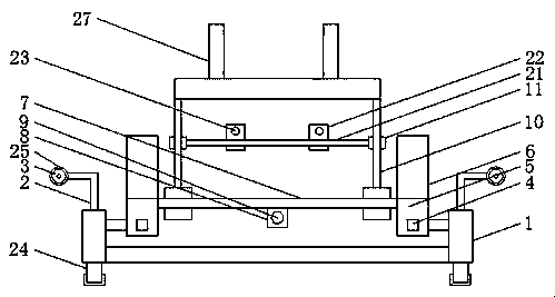
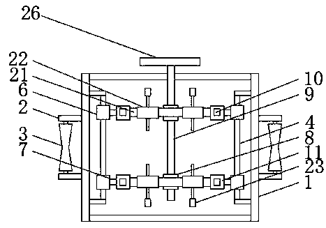
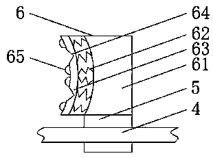
[0026] see Figure 1-5 , the present invention provides a technical solution: an orthopedic fixed bracket, including a base 1, a roller frame 2 is arranged on the left and right sides of the top of the base 1, a roller 3 is movable on the roller frame 2, and the left and right sides of the inner cavity of the base 1 Both sides are provided with a longitudinal slide bar 4, and the front and rear sides of the longitudinal slide bar 4 are movably sleeved with a l...


PUM


Abstract

The invention discloses a fixing bracket for the orthopedics department. The fixing bracket comprises a base, a clamping block comprises a clamping block body, and buffering springs are uniformly arranged on the left side of the clamping block body; a sterile silica gel mat is connected to the other ends of the buffering springs, reset springs are arranged on the right sides of inner cavities of grooves, and fixture blocks are connected to the left sides of the reset springs; a pushing rod is arranged on the left side of each fixture block, rubber mats are arranged on the right sides of fixingbolts, and the buffering springs have damping and buffering effects; formed open grooves can change the bending radian of the sterile silica gel mat, the contact area with limbs is increased, the force applied to the limbs is dispersed, and the injury caused to the limbs is relieved; a transverse sliding rod is rotated to change the angle of inserting a bone nail in the bone, and the fixture blocks are pushed through the tension of the reset springs; it is avoided that the fixing bolts are in direct contact with vertical upright frames through the rubber mats so as to damage the vertical upright frames, and the abrasion of threads on the fixing bolts and threaded holes is avoided.

Description

technical field [0001] The invention relates to the field of medical devices, in particular to an orthopedic fixation bracket and a fixation method. Background technique [0002] Nowadays, the most commonly used orthopedic fixator is the orthopedic fixator when treating long tubular bone fractures. The traditional orthopedic fixer is cumbersome and difficult to disassemble. In order to solve the above problems, it is necessary to design a new orthopedic fixer. [0003] Patent No. CN201621144009.0 discloses an orthopedic fixation frame, which not only has a simple structure, but also has an adjustable device during fixation, which is simple to fix and easy to disassemble. Two first connecting rods are connected between the two first square rods, the roller frame is connected with the first square rod by welding, the roller is installed on the roller frame, the slide rod frame is connected with the first square rod by welding, and the sliding rod frame is connected with the fi...

Claims


Application Information

Patent Timeline
Patent Type & Authority Applications(China)
IPC IPC(8): A61B17/64
CPCA61B17/6408A61B17/6416
Inventor 缪建强
Owner 苏州建益森电子科技有限公司
Why Eureka
Try Eureka