Core rod cooling process method and core rod cooling device

A cooling process and mandrel technology, used in manufacturing tools, metal processing equipment, metal rolling, etc., can solve the problem of uneven wall thickness of steel pipes, achieve accurate cooling effect, ensure uniformity, and meet the effect of cooling capacity

Pending Publication Date: 2018-11-06
JIANGSU CHANGBAO PLS STEEL TUBE
View PDF5 Cites 3 Cited by
  • Summary
  • Abstract
  • Description
  • Claims
  • Application Information

AI Technical Summary

Problems solved by technology

[0005] The first object of the present invention is to provide a cooling method for mandrels, which can accurately cool down the mandrels in the range of mandrel lengths used, and can achieve the uniformity of axial and radial cooling of mandrels, Improve the temperature uniformity of the mandrel after cooling, effectively solving the problem of uneven wall thickness of the steel pipe caused by the uneven temperature of the mandrel in the prior art

Method used


Image

  • Core rod cooling process method and core rod cooling device
  • Core rod cooling process method and core rod cooling device
  • Core rod cooling process method and core rod cooling device

Examples


Embodiment 1

[0064] The cooling process method of the mandrel described in the present embodiment, the steps are as follows:

[0065] (1) After the mandrel is dephosphorized, the mandrel is in the hollow box 1, passes through the ring center of the cooling ring 2, and advances along the axial direction of the mandrel at a speed of 1-2m / s, passing through the first temperature The detector 7 measures the temperature T of each place of the mandrel, and the temperature detector feeds back the measured temperature T of the mandrel to the PLC module, and the PLC module compares the temperature T with the preset temperature T 0 For comparison, the PLC module controls the opening and closing of the nozzles on the cooling rings in real time according to the comparison results, and adjusts the amount of air mist cooled by the mandrel along the axial direction according to the temperature T. The higher the temperature, the greater the amount of air mist , the lower the temperature, the smaller the a...

Embodiment 2

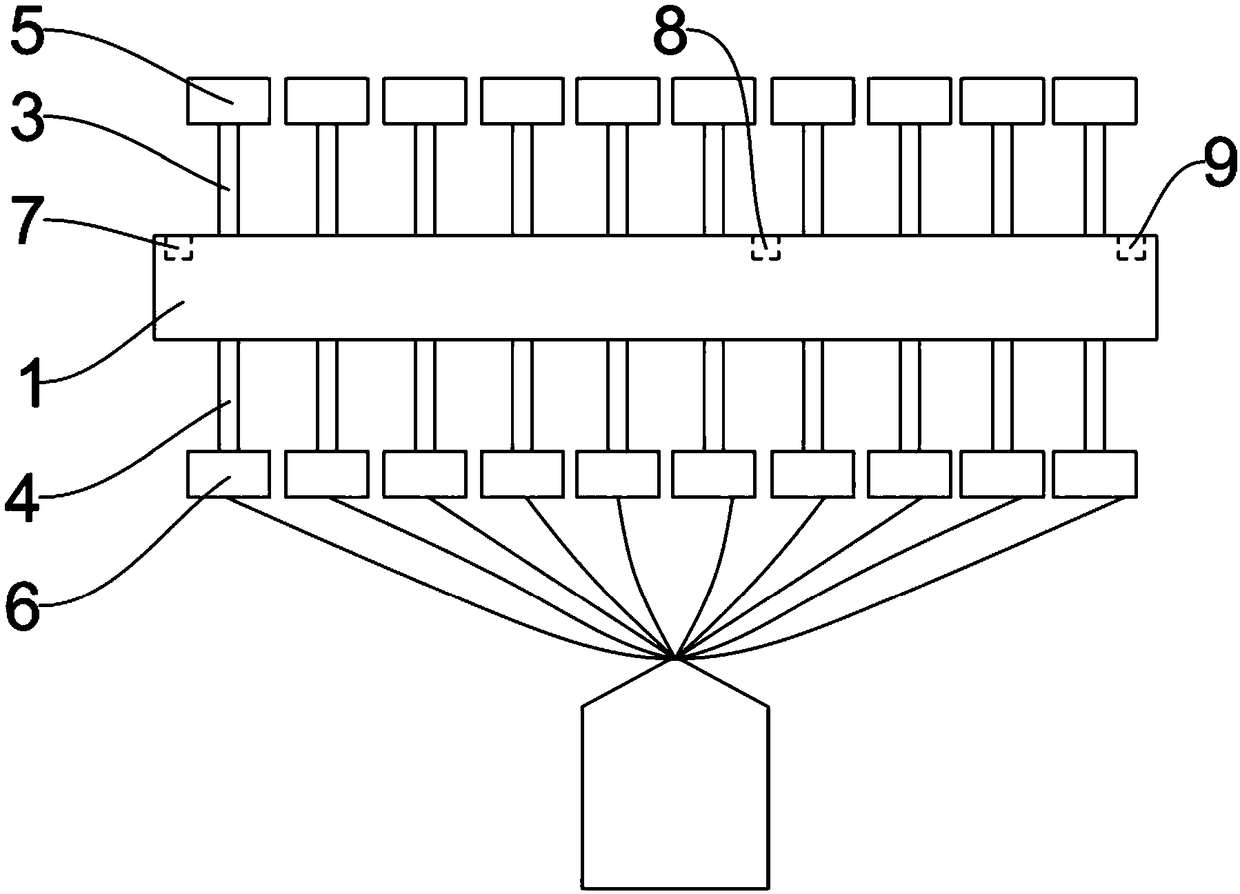
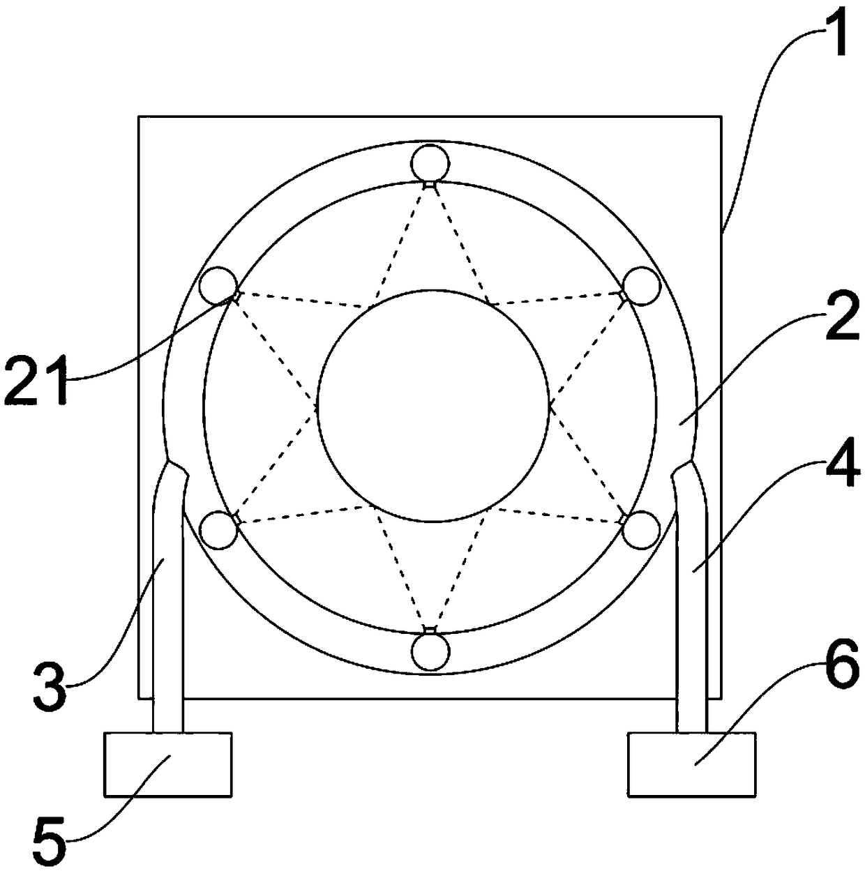
[0069] In this embodiment, the device with 10 cooling rings 2 arranged in parallel is taken as an example. The first temperature detector 7 is arranged before the first cooling ring, and the second temperature detector 8 is arranged at the sixth and seventh cooling rings. Between the rings, the third temperature detector 9 is arranged behind the tenth cooling ring. Six nozzles 21 are evenly arranged on the inner side of the cooling ring 2 along the circumferential direction of the cooling ring. The spray angle of the nozzles 21 is 30°, so The distance between the nozzle 21 and the mandrel is 105mm. Taking the use of a mandrel with a length of 10m as an example, the steps of the cooling process for the mandrel are as follows:

[0070](1) After the mandrel is dephosphorized, the mandrel is in the hollow box 1, passes through the center of the cooling ring 2, advances along the axial direction of the mandrel at a speed of 1.5m / s, and passes through the first temperature detection ...


PUM

PropertyMeasurementUnit
lengthaaaaaaaaaa
lengthaaaaaaaaaa
lengthaaaaaaaaaa

Abstract

The invention relates to the technical field of core rod cooling, in particular to a core rod cooling process method and a core rod cooling device. The core rod cooling process method comprises the following steps that air-fog cooling is carried out on a core rod, wherein the temperature T of the core rod is measured, and the subsection adjustment and control of the air fog amount of air-fog cooling is carried out on the core rod in the axial direction according to the temperature T. The core rod cooling device comprises a hollow box body, cooling rings arranged in parallel, air pipelines, water pipelines, temperature detectors and a controller. According to the actual temperature of the core rod in the axial direction, and according to the actual temperatures of different points, air-fogcooling with different gas-fog amounts is carried out on the core rod, so that the axial temperature of the core rod is accurately reduced, and the problems that the wall thickness of a product is uneven and the abrasion of the core rod is uneven due to the fact that the axial temperature of the core rod is uneven in the continuous rolling process is effectively solved.

Description

technical field [0001] The invention relates to the technical field of mandrel cooling, in particular to a mandrel cooling process method and a device thereof. Background technique [0002] The mandrel is an important tool and mold for the pipe jacking unit to participate in the deformation of the steel pipe, and its consumption is relatively large, and the quality and cost of the mandrel are directly related to the quality and benefit of steel pipe production. Among them, in the production process, the temperature uniformity of the mandrel directly affects the uniformity of the longitudinal wall thickness of the steel pipe and the wear uniformity of the mandrel itself. For example, the surface temperature of the mandrel is not uniform, resulting in uneven temperature of the inner wall of the steel pipe, inconsistent plastic deformation and slip of the metal, resulting in local thinner wall thickness and steel pipe defects. [0003] The mandrel is used in multiple online cy...

Claims


Application Information

Patent Timeline
Patent Type & Authority Applications(China)
IPC IPC(8): B21B25/04
CPCB21B25/04
Inventor 王国富王剑平王纯凯陆子龙马叶忠
Owner JIANGSU CHANGBAO PLS STEEL TUBE
Why Eureka
Try Eureka