Uniform gas flow gas inlet device and uniform gas inlet method for vapor deposition

A technology of gas phase deposition and air inlet, which is applied in the direction of gaseous chemical plating, metal material coating process, coating, etc., can solve the problems of uneven thickness and little influence on product uniformity, and achieve improved yield and improved Non-uniform wall thickness and easy operation

Active Publication Date: 2013-06-19
山东国晶新材料有限公司
View PDF5 Cites 0 Cited by
  • Summary
  • Abstract
  • Description
  • Claims
  • Application Information

AI Technical Summary

Problems solved by technology

At present, a commonly used vapor deposition furnace includes a furnace body, a heating body, an air inlet, an air outlet, and a mould. , connected with an external motor to rotate, the shape of the air outlet is generally bell-shaped, or a three-dimensional bell-shaped with two parallel planes, this type of air inlet is used for the production of plates or small-sized crucible products. The uniformity of the mold has little effect; but when producing pyrolytic boron nitride crucible products with a long length, the gas is easy to accumulate near the air inlet of the mold, resulting in uneven thickness of different parts of the crucible

Method used


Image

  • Uniform gas flow gas inlet device and uniform gas inlet method for vapor deposition
  • Uniform gas flow gas inlet device and uniform gas inlet method for vapor deposition
  • Uniform gas flow gas inlet device and uniform gas inlet method for vapor deposition

Examples


Embodiment 1

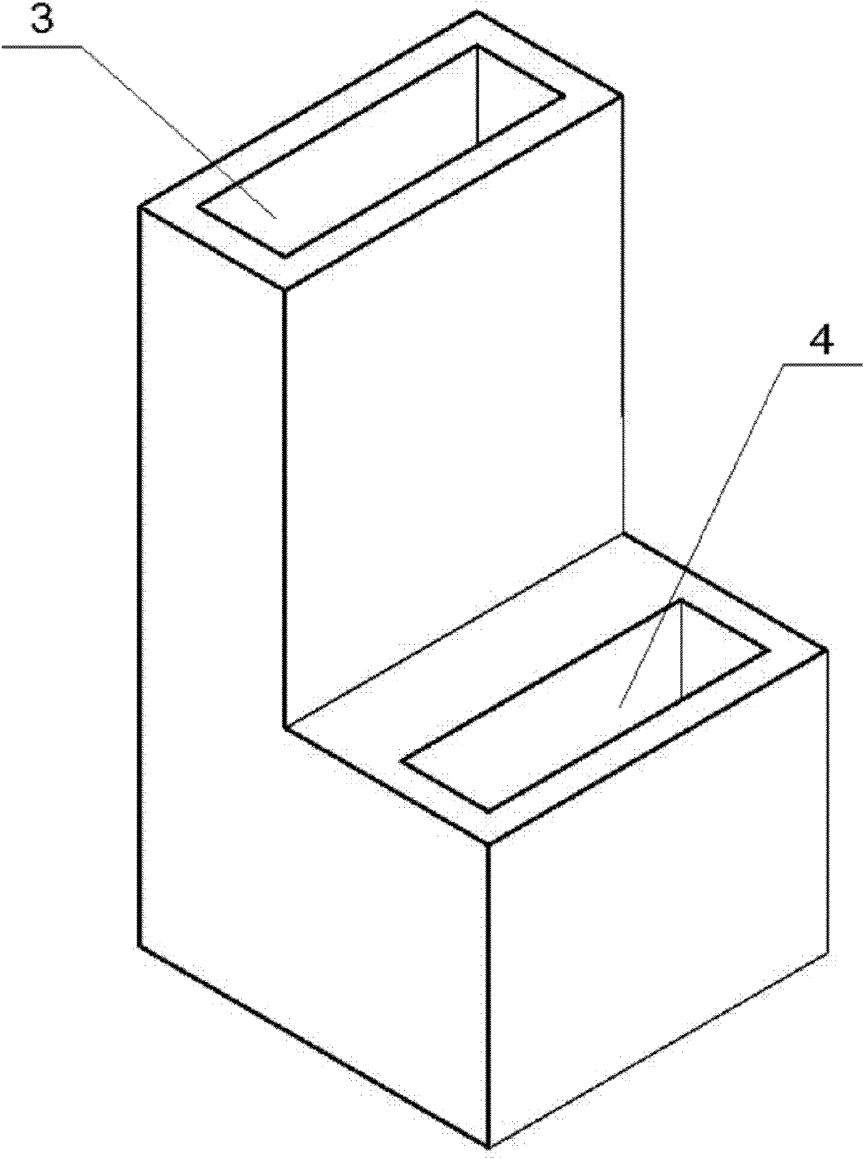
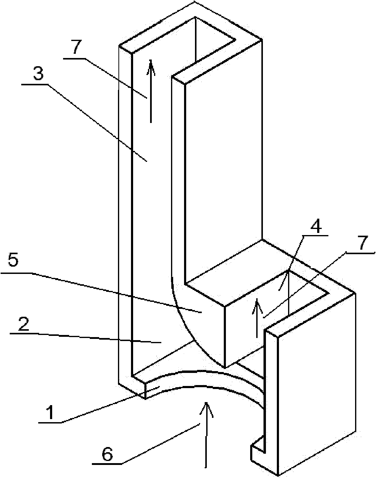
[0027] see Figure 1-2 , a uniform gas flow inlet device for vapor deposition, its overall shape is "L" shape, the gas inlet device includes a raw material gas mixing chamber 2 with a circular hole-shaped inlet hole 1, and a mixing chamber 2 Connected cuboid air outlet channels 3 and 4 have the same air outlet direction and different lengths, and the length ratio of the two air outlet channels is 1:0.4.

[0028] In the mixing chamber 2, a deflector is arranged at the position where the two outlet passages 3, 4 are connected to the mixing chamber 2, and the deflector is connected to the two outlet passages respectively; the cross-sectional shape of the deflector is It is in the shape of a right-angle fan, and the right-angle side of the right-angle fan-shaped deflector 5 is connected to the shorter air outlet channel 4, and the arc side of the right-angle fan-shaped deflector 5 is connected to the longer air outlet channel 3.

[0029] The air intake direction of the air inlet ...

Embodiment 2

[0031] The air inlet device as described in Embodiment 1 is different in that: the length ratio of the two air outlet channels 3 and 4 is 1:0.5.

Embodiment 3

[0033] A method for using the above-mentioned air inlet device for uniform air intake in a vapor deposition reaction, comprising placing the above-mentioned air inlet device at the air inlet of a vapor deposition furnace, and making the distance between the mold in the vapor deposition furnace and the air inlet The short air outlet channel mouth 2 centimeters in the device, the longer air outlet channel 3 is located on one side of the mould.


PUM


Abstract

The invention discloses a uniform gas flow gas inlet device for vapor deposition, which comprises a raw gas mixing cavity and two gas outlet passages, wherein the raw gas mixing cavity is provided with a gas inlet hole, the gas outlet passages are communicated with the mixing cavity and have the same gas outlet direction and different lengths, and the length proportion of the two gas outlet passages is 1:(0.3-0.6). The uniform gas flow gas inlet device has the advantages that reaction gas enters the mixing cavity through the gas inlet hole, gas is discharged to a mold in a deposition furnace through the two gas outlet passages, because the two gas outlet passages have different lengths, the longer gas outlet passage guides gas to flow to the middle of the mold, outlet gas can be uniformlydispersed and deposited onto all positions of the mold, the defect that the gas is gathered at the bottom of a crucible and is difficult to reach the upper part of the crucible to be deposited because the crucible is long is overcome, and the finished product rate of the produced crucible products is greatly improved.

Description

technical field [0001] The invention relates to a uniform airflow inlet device and a uniform airflow method for vapor deposition, and belongs to the technical field of producing pyrolysis boron nitride crucible products by vapor deposition. Background technique [0002] In recent years, due to its excellent properties such as high thermal conductivity, electrical insulation, and strong chemical inertness, pyrolytic boron nitride is very suitable for use as materials for crucibles, high-temperature fixtures, electronic component substrates, and dielectrics. Chemical vapor deposition (CVD) is the most commonly used method for producing pyrolytic boron nitride, and the pyrolytic boron nitride crucible products prepared by this method have good machinability and can well meet the application requirements. At present, a commonly used vapor deposition furnace includes a furnace body, a heating body, an air inlet, an air outlet, and a mould. , connected with an external motor to r...

Claims


Application Information

Patent Timeline
Patent Type & Authority Patents(China)
IPC IPC(8): C23C16/455
Inventor 刘汝萃刘汝强
Owner 山东国晶新材料有限公司
Why Eureka
Try Eureka