Valve fastening device

A technology for fastening devices and valves, applied in hand-held tools, manufacturing tools, etc., can solve problems such as hindering staff from walking around and difficult valve operation, and achieve the effects of improving traffic smoothness, convenient and labor-saving construction, and convenient carrying and storage

Inactive Publication Date: 2018-11-06
JINGXI XIUMEI BIANCHENG AGRI SCI & TECH CO LTD
View PDF6 Cites 0 Cited by
  • Summary
  • Abstract
  • Description
  • Claims
  • Application Information

AI Technical Summary

Problems solved by technology

[0003] Although the scheme of extending the small shaft of the valve solves the problem of difficult operation of the valve, the height of the valve after the extension of the small shaft of the valve is higher than the flower iron plate, which hinders the staff from walking on the flower iron plate

Method used


Image

  • Valve fastening device
  • Valve fastening device
  • Valve fastening device

Examples


Embodiment Construction

[0029] The specific implementation of the invention will be further described below in conjunction with the accompanying drawings.

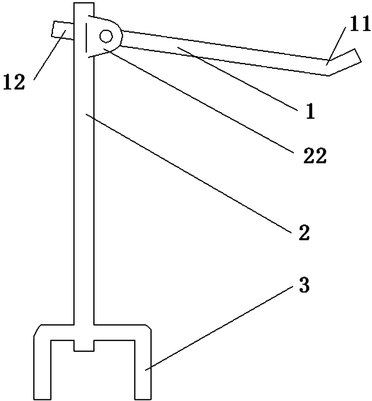
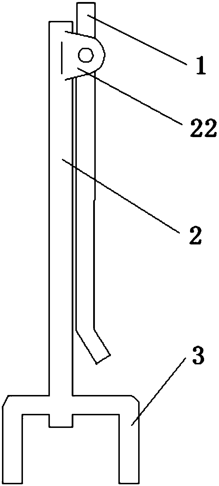
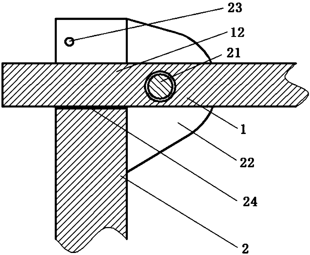
[0030] Such as figure 1 and Figure 5 As shown, the present invention provides a valve fastening device, including a push rod 1, a vertical rod 2 and a handle 3, wherein, as image 3 As shown, the top of the vertical rod 2 is provided with a pivot pin connection device and a U-shaped groove 24, the pivot pin connection device is arranged on the side of the vertical rod 2, the U-shaped groove 24 is arranged on the end face of the vertical rod 2, and the pivot pin connection device includes two lugs. The plate 22 is connected to a shaft pin 21, and the two ear plates 22 are fixedly connected to the vertical rod 2. The push rod 1 includes two ends, which are respectively the force application end 11 and the connecting end 12. The push rod 1 is connected to the shaft pin 21 through the connecting end 12, Realize rotational connection with pole 2. ...


PUM


Abstract

The invention discloses a valve fastening device and belongs to the field of fastening devices for mechanical workpieces. The valve fastening device comprises a push rod, a vertical rod and a handle.One end of the vertical rod is provided with a shaft pin connection device and a U-shaped groove, and the U-shaped groove is provided with an angle clamping piece. The push rod is rotatably connectedwith the vertical rod, and the other end of the vertical rod is fixedly connected with the handle. By means of the valve fastening device provided by the invention, the problem that a valve parallel to a checkered iron plate is difficult to switch on and switch off is solved, and the valve fastening device has the characteristics of being convenient to carry and store, convenient to construct andthe like.

Description

technical field [0001] The invention relates to the field of fastening devices for mechanical workpieces, in particular to a valve fastening device for flushing iron plates. Background technique [0002] In the engine room of ships and offshore platforms, when valves such as emergency suction valves of seawater pumps are arranged, in order to avoid hindering the walking of personnel, the valves can only be arranged flush with the flower iron plate. This causes difficulty in operation and cannot achieve the effect of opening and closing the valve. The current existing solution is to reprocess the transmission shaft and extend the small shaft of the valve, so that the valve is higher than the flower iron plate, which is convenient for personnel to operate. [0003] Although the scheme of extending the small shaft of the valve solves the problem of difficult operation of the valve, the height of the valve is higher than the flower iron plate after the valve small shaft is exte...

Claims


Application Information

Patent Timeline
Patent Type & Authority Applications(China)
IPC IPC(8): B25B33/00
CPCB25B33/00
Inventor 韩再满
Owner JINGXI XIUMEI BIANCHENG AGRI SCI & TECH CO LTD
Why Eureka
Try Eureka