Quadruped robot

A quadruped robot, the body technology, applied in the direction of motor vehicles, transportation and packaging, etc., can solve the problems of inability to expand and contract, easy to overturn, robot easy to overturn, etc.

Active Publication Date: 2018-11-06
SHANDONG UNIV
View PDF7 Cites 12 Cited by
  • Summary
  • Abstract
  • Description
  • Claims
  • Application Information

AI Technical Summary

Problems solved by technology

[0002] With the development of technology, quadruped robots have been used in more and more fields. In the existing quadruped robots, the calf part cannot be stretched relative to most of the thighs.
When a quadruped robot moves on uneven ground, such as pitted ground, slopes, steps, etc., stability control is more difficult

Method used


Image

  • Quadruped robot
  • Quadruped robot
  • Quadruped robot

Examples


Embodiment 1

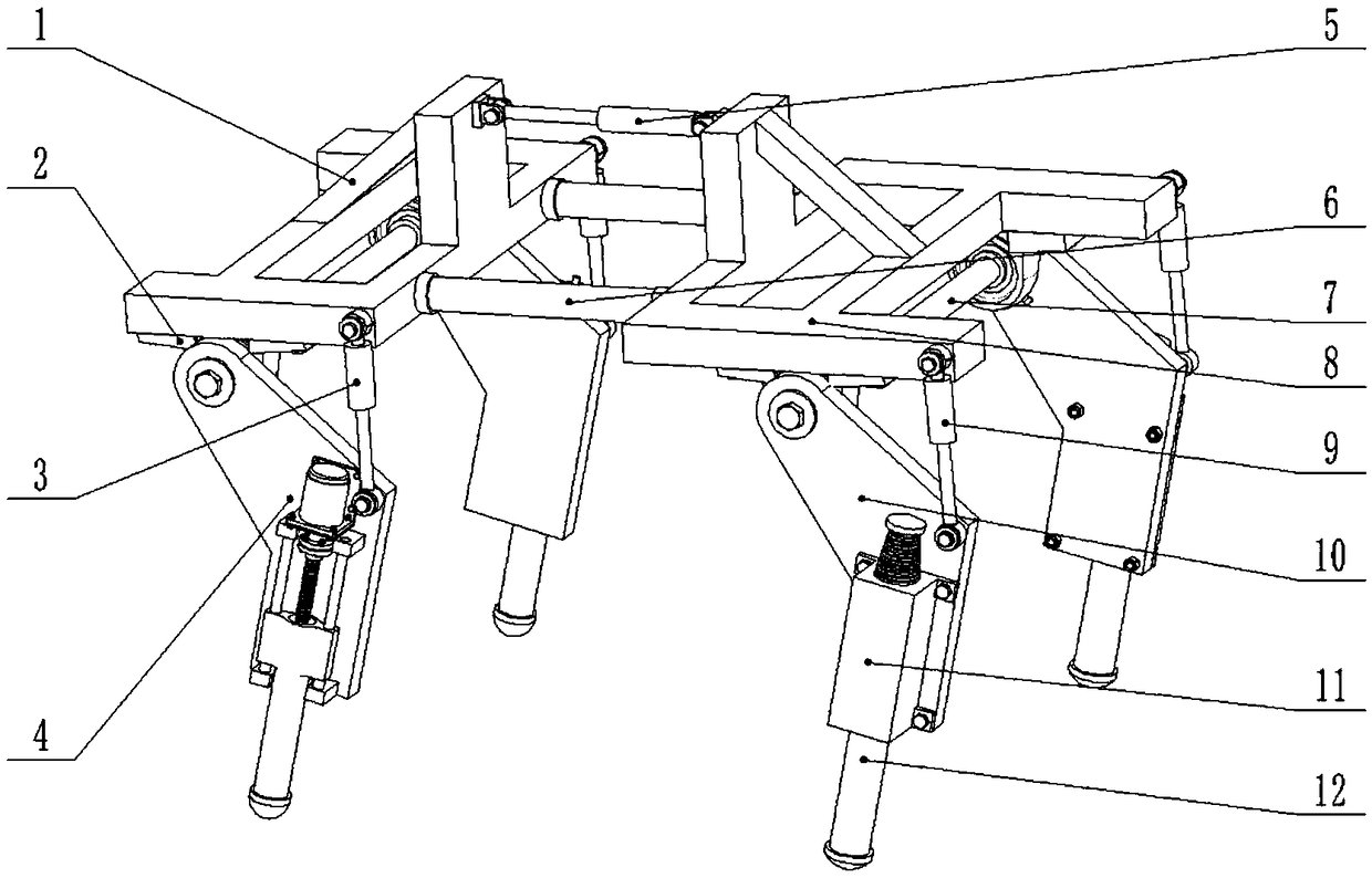
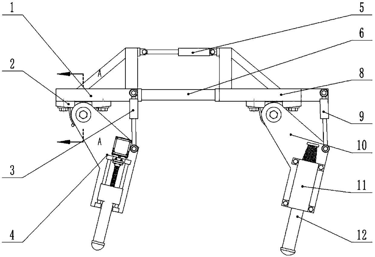
[0029] In a typical implementation of the present application, such as figure 1 As shown, the quadruped robot includes a front body 8 and a rear body 1, the front body 8 and the rear body 1 are connected by an elastic device, and a driving cylinder is also provided between the front body 8 and the rear body 1 5. Realize the relative rotation between the front body 8 and the rear body 1 by inflating and deflating the driving cylinder 5, so as to realize the straightening or bending of the body, so that the body is flexible; when the driving cylinder is deflated, the front body 8 and the rear body 1 is bent, and when the driving cylinder is inflated, the front body 8 and the rear body 1 are straightened.

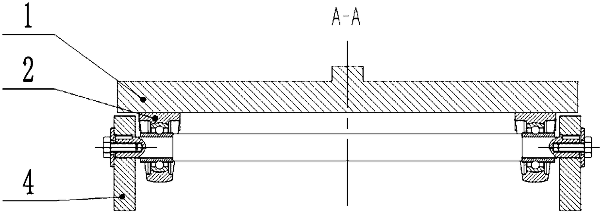
[0030] Two front outriggers are installed on the front body 8, and two rear outriggers are installed on the rear body 1, and the two front outriggers and the two rear outriggers are respectively installed on a rotating shaft to realize the rear outrigger Relative to the swing...

Embodiment 2

[0041] The front outrigger and the rear outrigger in the present embodiment adopt the same driving mode; the described front outrigger and the rear outrigger respectively comprise a thigh and a shank, and an electromagnet is installed on the thigh, and the The lower leg is installed in the electromagnet, and the rear part of the lower leg is connected with the thigh through an elastic device; when the electromagnet is energized, the lower leg stretches out to achieve the effect of extending the length of the leg; when the electromagnet is de-energized , the lower leg is pulled up under the action of the elastic device to achieve the effect of shortening the length of the leg; the rest is the same as in embodiment 1.

Embodiment 3

[0043] The front outrigger and the rear outrigger in this embodiment adopt the same driving mode; the described front outrigger and the rear outrigger respectively include a thigh and a lower leg, and a motor is installed on the thigh, so The motor described above drives a lead screw to rotate through a shaft coupling, and the shank cooperates with the lead screw through threads, the lead screw rotates, and the shank stretches up and down; the rest is the same as that of embodiment 1.


PUM


Abstract

The invention discloses a quadruped robot. The quadruped robot comprises a front robot body and a rear robot body; the front robot body is connected with the rear robot body through an elastic device;a driving cylinder is also arranged between the front robot body and the rear robot body; relative rotation between the front robot body and the rear robot body is realized by inflating and deflatingthe driving cylinder so as to realize straightening or bending of the robot body; two front outriggers are mounted on the front robot body; two rear outriggers are mounted on the rear robot body; thetwo front outriggers and the two rear outriggers are correspondingly mounted on one rotating shaft so as to realize the swinging of the rear outriggers relative to the rear robot body and the swinging of the front outriggers relative to the front robot body; and shank parts of the front outriggers and the rear outriggers can expand and retract relative to corresponding thigh parts.

Description

technical field [0001] The invention discloses a quadruped robot. Background technique [0002] With the development of technology, quadruped robots have been applied in more and more fields. In the existing quadruped robots, the calf part cannot be stretched relative to most of the thighs. When a quadruped robot moves on uneven ground, such as pitted ground, slopes, steps, etc., stability control is more difficult than on flat ground, mainly because the robot is prone to tipping over, which greatly reduces the stability of the robot. At present, the bodies of quadruped robots are mostly rigid, which makes the bodies of quadruped robots lack flexibility when walking or running, resulting in insufficient stability and easy to fall over. Contents of the invention [0003] In order to solve the technical problems in the prior art, the invention discloses a quadruped robot. [0004] The technical scheme disclosed by the present invention is as follows: [0005] A quadruped ...

Claims


Application Information

Patent Timeline
IPC IPC(8): B62D57/032
CPCB62D57/032
Inventor 马宗利马庆营吕荣基王建明
Owner SHANDONG UNIV
Why Eureka
Try Eureka