Novel long-range fire fighting monitor

A fire-fighting water cannon and long-range technology, which is applied in fire rescue and other directions, can solve the problems of small axial speed, easy topple over, large energy loss, etc., and achieve a smooth exit flow state, easy loading and transportation, and small loss in the pipe Effect

Inactive Publication Date: 2016-08-31
JIANGSU UNIV
View PDF10 Cites 3 Cited by
  • Summary
  • Abstract
  • Description
  • Claims
  • Application Information

AI Technical Summary

Problems solved by technology

In order to achieve rotation in the horizontal and vertical directions, the fire water monitor usually contains at least three 90° elbow structures, and the existence of the elbow will not only generate secondary flow, but also form an obvious gap in the outlet pipe section of the water monitor. Rotating around the flow, even if there is a flow stabilizer for rectification to obtain a uniform nozzle flow, the energy loss is quite large, the axial speed is small, and the range often cannot achieve the desired effect. The structure of ordinary fire water monitors has a high center of gravity, which is easy to Overturning, causing vibration, seriously affecting the service life of the water monitor
The steering mode of the fire water monitor mainly adopts three types: the handle drives the worm gear mechanism, the motor drives the worm gear mechanism, and the hydraulically drives the worm gear mechanism. The fire water monitor with the handle drives the worm gear mechanism is difficult to control the pitch and rotation, which affects the efficiency of firefighting operations; The motor-driven worm gear mechanism will cause the water cannon to strike due to water entering the motor;

Method used


Image

  • Novel long-range fire fighting monitor
  • Novel long-range fire fighting monitor
  • Novel long-range fire fighting monitor

Examples


Embodiment Construction

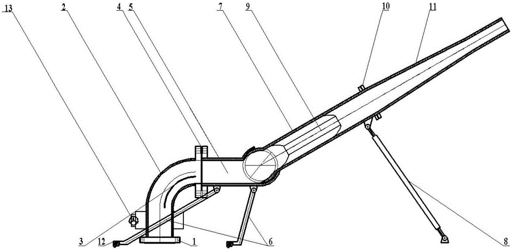
[0031] now attached Figure 1-8 Further description of the technical solution of the present invention:

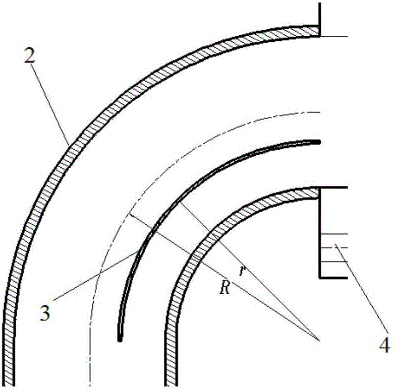
[0032] combined with figure 1 , the water inlet pipe 2 is a 90° arc, and includes two straight pipe sections and an arc section, and a worm gear mechanism is arranged on the outside of the vertical straight pipe section. The lower side of the pipe section is provided with a flange A1 for combining with other pipes. The arc section is a 90° arc, and a guide vane 3 is provided at the 90° arc. The guide vane 3 is concentric with the 90° arc. The radius of curvature of the axis of the elbow is 170 mm, and the welding position of the deflector 3 is located in the half channel near the center of the elbow, and the distance from the axis is 20 mm. The pipelines of the dynamic joint pipe 7 and the static joint pipe 5 adopt circular straight pipes except for the spherical surface; There is a gap between them, and the gap is sealed by bearing pressure plate and rubber; the diamet...


PUM


Abstract

The invention discloses a novel long-range fire fighting monitor including: a water inlet pipe, a static joint pipe, a movable joint pipe and a water outlet pipe. A water outlet end of the water inlet pipe is detachably connected to a water inlet end of the static joint pipe through a flange B. The water outlet end of the static joint pipe is connected to the water inlet of the movable joint pipe. The water outlet end of the movable joint pipe is detachably connected to the water outlet pipe through a flange C. The water inlet pipe is in the shape of a circular arc in certain angle, wherein a turbine worm mechanism is arranged on the outer side of the water inlet pipe, so that the water inlet pipe can be rotated horizontally by rotating a worm handle. A circular-arc-shaped flow guide sheet being concentric with the water inlet pipe is disposed in the water inlet pipe, wherein two sides of the flow guide sheet are welded to the side wall of the water inlet pipe. The static joint pipe is connected to the movable joint pipe in manner of spherical connection with one sphere center, wherein the inner surface spherical diameter of the static joint pipe is larger than the outer spherical diameter of the movable joint pipe. The fire fighting monitor is low in internal loss, has a compact structure, is not liable to tip, has a smooth outlet flow status and has long shoot range.

Description

technical field [0001] The invention relates to the technical field of fire-fighting water cannons, in particular to a novel long-range fire-fighting water cannon. Background technique [0002] Fire water cannon has become the most common fire extinguishing equipment because of its large flow and long range. In addition, it also plays a deterrent role in territorial waters security, expulsion of illegal maritime industries and pirates, etc. Water cannons replace arms, which is environmentally friendly and Avoid local wars. In order to achieve rotation in the horizontal and vertical directions, the fire water monitor usually contains at least three 90° elbow structures, and the existence of the elbow will not only generate secondary flow, but also form an obvious gap in the outlet pipe section of the water monitor. Rotating around the flow, even if there is a flow stabilizer for rectification to obtain a uniform nozzle flow, the energy loss is quite large, the axial speed is...

Claims


Application Information

Patent Timeline
Patent Type & Authority Applications(China)
IPC IPC(8): A62C31/00
CPCA62C31/00
Inventor 袁丹青石荣丛小青王航季明张楠
Owner JIANGSU UNIV
Why Eureka
Try Eureka