
Wire winding device and leading wire drying system

A technology of a wire take-up device and a mounting frame, which is applied in the directions of transportation and packaging, transportation of filamentous materials, and processing of thin materials, can solve problems such as poor anti-failure ability, and achieve the effect of improving anti-failure ability.

Pending Publication Date: 2018-11-06
CHANGSHA YUEQI ENERGY SAVING ELECTRICAL EQUIP CO LTD
View PDF0 Cites 2 Cited by
  • Summary
  • Abstract
  • Description
  • Claims
  • Application Information

AI Technical Summary

Problems solved by technology

[0005] The main purpose of the present invention is to provide a wire take-up device, which aims to solve the technical problems in the related art that the wires of the wire winding structure interfere with each other and have poor anti-fault ability

Method used


Image

  • Wire winding device and leading wire drying system
  • Wire winding device and leading wire drying system
  • Wire winding device and leading wire drying system

Examples


no. 1 example

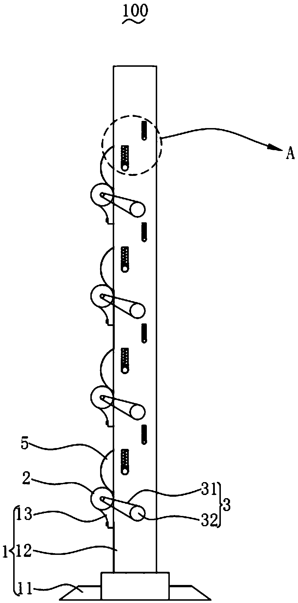
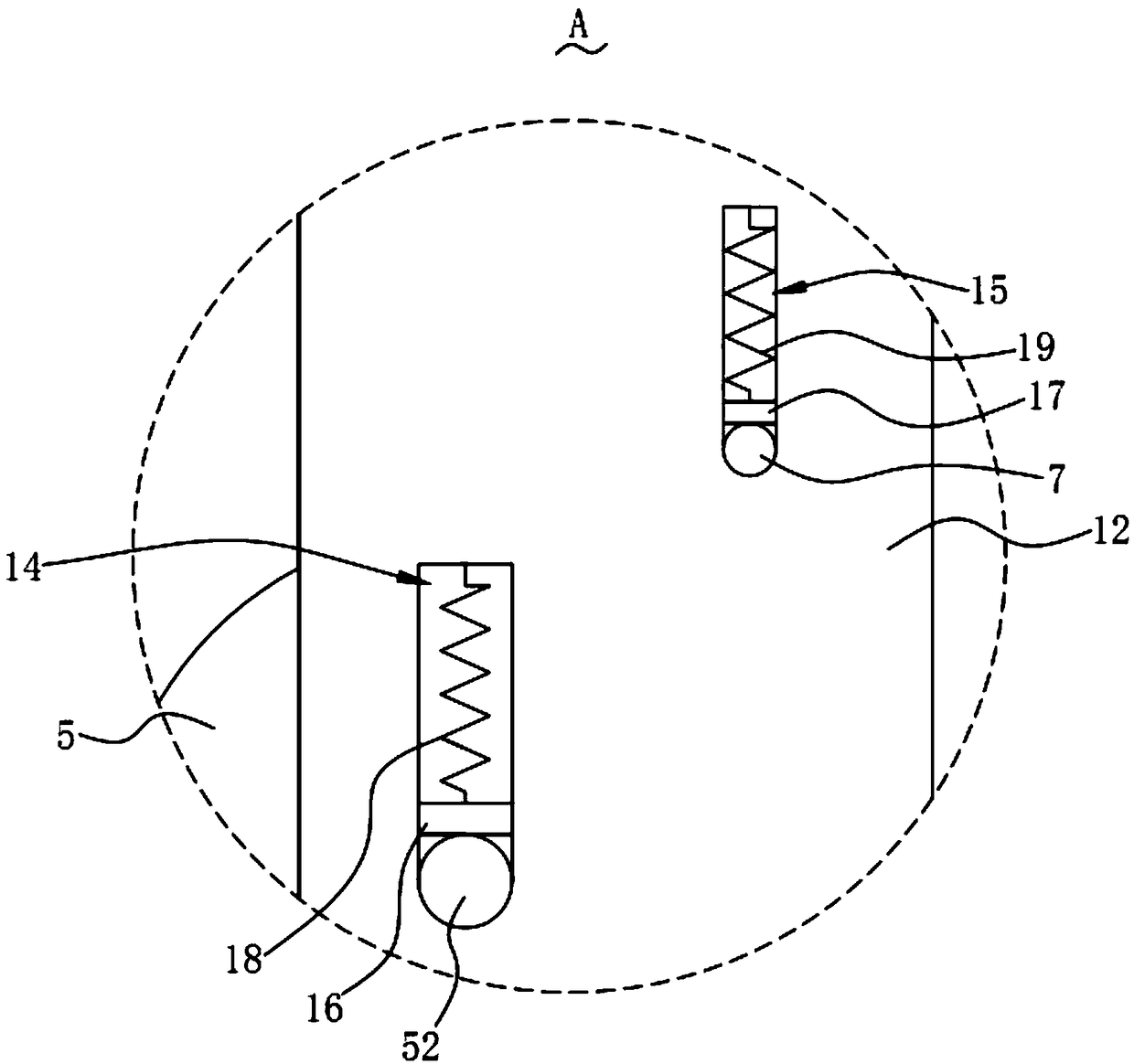
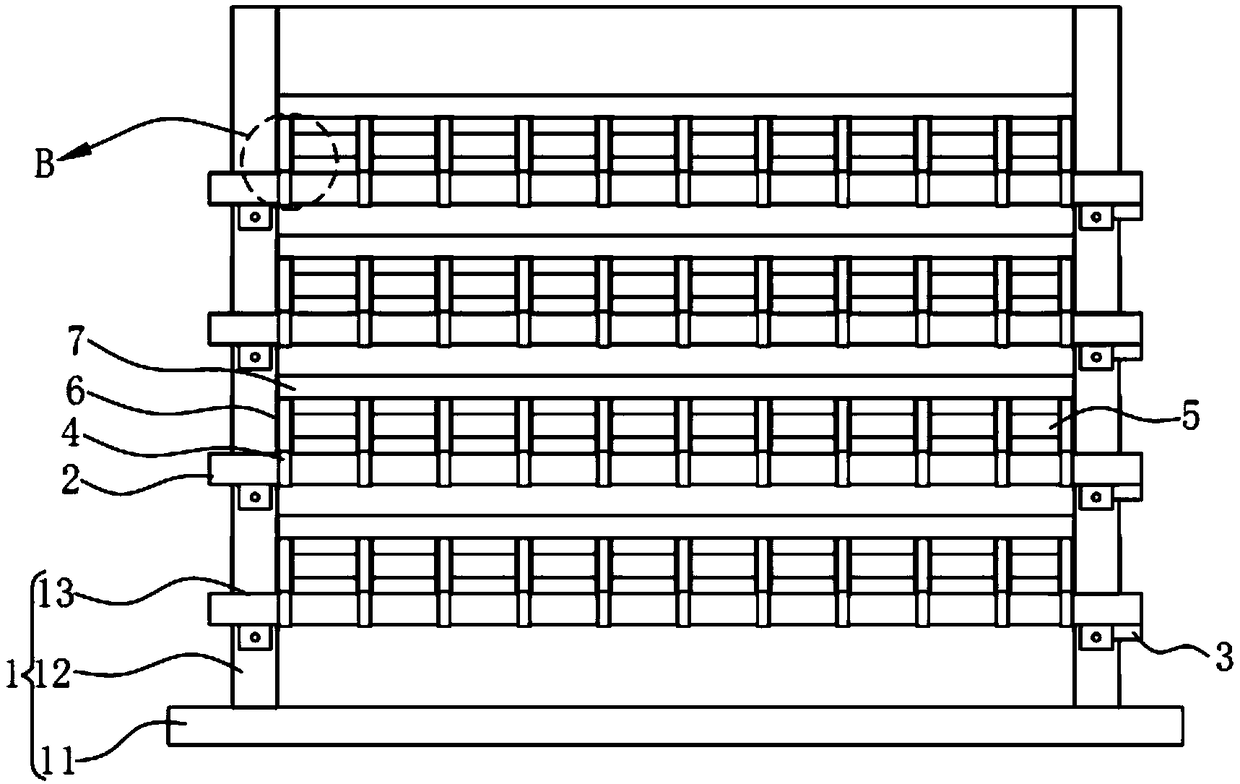
[0045] Please refer to Figure 1-4 , in one embodiment of the present invention, the wire take-up device 100 includes:

[0046] Mounting frame 1;

[0047] A drive shaft 2, the drive shaft 2 is rotationally connected with the installation frame 1;

[0048] A drive assembly 3, the drive assembly 3 is used to drive the drive shaft 2 to rotate;

[0049] A plurality of embossing wheels 4, and the embossing wheels 4 are arranged around the drive shaft 2;

[0050] The bobbin 5 is rotatably connected to the mounting frame 1;

[0051] A plurality of rotating rings 6, the rotating rings 6 are arranged around the winding shaft 5, and the first ends of two adjacent rotating rings 6 clamp an embossing wheel 4;

[0052] Driven shaft 7, driven shaft 7 is rotationally connected with mounting frame 1, and driven shaft 7 abuts against the second end of rotating ring 6; wherein, drive shaft 2, drive assembly 3, winding shaft 5 and driven shaft 7 equal in number.

[0053]The wire take-up de...

no. 2 example

[0065] Please refer to Figure 7-9 Based on the wire take-up device 100 provided in the first embodiment of the present invention, another wire take-up device 101 provided in the second embodiment of the present invention is different in that the wire take-up device 101 also includes a spare shaft 8 and Switch frame 9, switch frame 9 comprises the first frame body 91, the second frame body 92, the 3rd frame body 93 and the 4th frame body 94, the second frame body 92 and the 3rd frame body 93 are arranged at the first At the two ends of the frame body 91, one end of the fourth frame body 94 runs through the mounting frame 1, and the other end of the fourth frame body 94 is connected with the first frame body 91, and the fourth frame body 94 is set away from the second frame body 92. The second frame body 92 is inserted into the winding shaft 5 , and the third frame body 93 is inserted into the spare shaft 8 .

[0066] Thereby it is convenient to switch when the winding shaft 5...


PUM


Abstract

The invention discloses a wire winding device and a leading wire drying system. The wire winding device comprises a mounting rack, driving shafts, driving assemblies, embossing printing wheels, wire winding shafts, rotary rings and driven shafts, wherein the driving shafts are rotatably connected with the mounting rack; the driving assemblies are used for driving the driving shafts to rotate; theembossing printing wheels are arranged around the driving shafts; the wire winding shafts are rotatably connected with the mounting rack; the rotary rings are arranged around the wire winding shafts;the first ends of the two adjacent rotary rings clamp one embossing printing wheel; the driven shafts are rotatably connected with the mounting shaft; the driven shafts abut against the second ends ofthe corresponding rotary rings; the number of the driving shafts, the number of the driving assemblies, the number of the wire winding shafts and the number of the driven shafts are equal. The wire winding shafts of the wire winding device provided by the invention rotate to conduct wire winding without mutual interference. The fault resistance of the wire winding device is high.

Description

technical field [0001] The invention relates to the technical field of fireworks production equipment, in particular to a wire take-up device and a wire drying system. Background technique [0002] Firecrackers and fireworks are people's favorite festive consumer products, which can bring joy to people and add color to holidays. With the continuous improvement of people's living standards, the output of firecrackers and fireworks has also increased rapidly. The lead wire is an important part in the manufacture of firecrackers and fireworks. It not only requires good quality, but also consumes a lot. Moreover, the lead wire is inflammable. In order to prevent the lead wire from burning or even explode, and to ensure the safety of lead wire production, it is necessary to dry the lead wire. [0003] In the related art, the wire take-up device of the lead wire drying system includes multiple winding mechanisms, and the multiple winding mechanisms are driven by a single driving...

Claims


Application Information

Patent Timeline
Patent Type & Authority Applications(China)
IPC IPC(8): B65H54/24B65H54/74B65H71/00
CPCB65H54/24B65H54/74B65H71/00B65H2701/36
Inventor 刘若平刘君美付东良肖湘杰
Owner CHANGSHA YUEQI ENERGY SAVING ELECTRICAL EQUIP CO LTD
Learn More