
Electromagnetic lifting tool for unmanned crane

A crane and electromagnetic technology, which is applied in the field of spreaders, can solve the problems of wasting working time and reducing efficiency, and achieve the effects of improving efficiency, increasing the suction contact area, and increasing the suction force

Active Publication Date: 2018-11-06
BAOSTEEL ZHANJIANG IRON & STEEL CO LTD +1
View PDF6 Cites 4 Cited by
  • Summary
  • Abstract
  • Description
  • Claims
  • Application Information

AI Technical Summary

Problems solved by technology

1. Regardless of whether it is a double-hook telescopic clamp or a C-shaped hook, it is necessary to align the hook with the steel coil hole and insert it during the lifting operation, resulting in a decrease in efficiency; 2. For the double-hook telescopic clamp, when lifting and After lifting and unloading in place, it is necessary to condense or extend the legs of the tongs, which wastes a certain amount of work time
3. For the C-shaped hook, due to the limited structure, it is difficult to apply it to unmanned cranes

Method used


Image

  • Electromagnetic lifting tool for unmanned crane
  • Electromagnetic lifting tool for unmanned crane
  • Electromagnetic lifting tool for unmanned crane

Examples


Embodiment Construction

[0027] The accompanying drawings are for illustrative purposes only, and should not be construed as limitations on this patent; in order to better illustrate this embodiment, certain components in the accompanying drawings will be omitted, enlarged or reduced, and do not represent the size of the actual product; for those skilled in the art It is understandable that some well-known structures and descriptions thereof may be omitted in the drawings. The positional relationship described in the drawings is for illustrative purposes only, and should not be construed as a limitation on this patent.

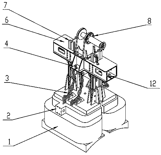
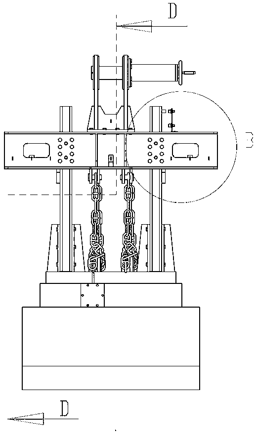
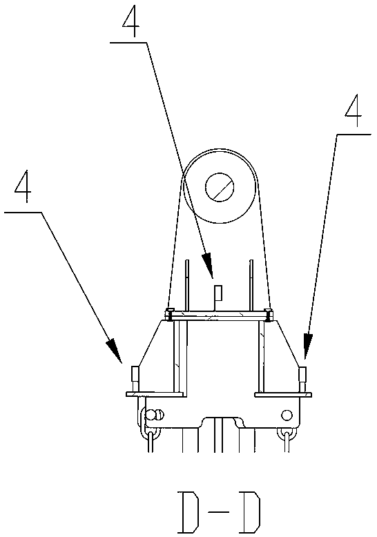
[0028] Such as figure 1 As shown, an electromagnetic spreader for an unmanned crane includes a beam 7 and an electromagnetic chuck 1 located below the beam 7, wherein two guide rails are arranged symmetrically at both ends of the beam 7, and the guide rails are perpendicular to the beam 7 Setting, guide rail is provided with groove, is provided with guide wheel group 5 in crossbeam 7...


PUM


Abstract

The invention relates to the field of lifting tools, in particular to an electromagnetic lifting tool for an unmanned crane. The electromagnetic lifting tool comprises a transverse beam for crane lifting; a space below the transverse beam is connected with an electromagnetic sucking disc; the sucking surface of the bottom of the electromagnetic sucking disc is a cambered surface; and transverse position detection instruments and longitudinal position detection instruments are arranged on the transverse beam. A sucking contact area and suction force can be increased; the electromagnetic suckingdisc can be guaranteed to be accurately aligned to the center line of a steel coil; and the problem that the steel coil of a single-plane sucking disc slides and rolls due to imbalance of a lifting center is solved.

Description

technical field [0001] The invention relates to the field of spreaders, in particular to an electromagnetic spreader for unmanned cranes. Background technique [0002] At present, there are mainly two types of hangers used for lifting steel coils, one is the lifting method using telescopic pincer legs with double hooks, and the other is the C-shaped hook method. The deficiencies of the prior art mainly include several points. 1. Regardless of whether it is a double-hook telescopic clamp or a C-shaped hook, it is necessary to align the hook with the steel coil hole and insert it during the lifting operation, resulting in a decrease in efficiency; 2. For the double-hook telescopic clamp, when lifting and After lifting and unloading in place, it is necessary to condense or expand the legs of the tongs, which wastes a certain amount of work time. 3. For the C-shaped hook, it is difficult to apply it to unmanned cranes due to the limited structure. Contents of the invention ...

Claims


Application Information

Patent Timeline
Patent Type & Authority Applications(China)
IPC IPC(8): B66C1/06
CPCB66C1/06
Inventor 姜中友袁喜弟梁业杨曙强周亚新陆士龙熊坤段建强孔利明姜玉河毛展宏
Owner BAOSTEEL ZHANJIANG IRON & STEEL CO LTD
Learn More