Hydraulic control sliding sleeve

A sliding sleeve and hydraulic technology, applied in the direction of wellbore/well components, earthwork drilling, sealing/isolation, etc., can solve the problems of inability to efficiently realize multiple repeated switches, inconvenient exploration wells, cumbersome operations, etc., to achieve guaranteed The effect of smooth operation and sealing reliability, convenient switch operation, and simplified operation

Pending Publication Date: 2018-11-06
HUNAN VICTOR PETROTECH SERVICE
View PDF0 Cites 3 Cited by
  • Summary
  • Abstract
  • Description
  • Claims
  • Application Information

AI Technical Summary

Problems solved by technology

Ordinary sliding sleeves are operated by steel wires, using switch tools to realize the opening and closing of sliding sleeves. For a sliding sleeve, it is generally necessary to configure two control pipelines, one for opening and one for closing. This operation is cumbersome and labor-intensive. The quantity is large, and repeated switching cannot be realized efficiently, especially for exploratory wells that require repeated testing operations.

Method used


Image

  • Hydraulic control sliding sleeve
  • Hydraulic control sliding sleeve
  • Hydraulic control sliding sleeve

Examples


Embodiment Construction

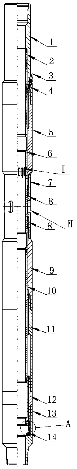
[0020] Such as figure 1 , figure 2 As shown, the hydraulic control sliding sleeve provided by the present invention includes an upper joint 1, a driving cylinder 5, a middle joint 7, a first transition joint 9, a cylinder body 11, a second transition joint 12, and a lower joint 13, which are sequentially Threaded connection and sealing; the driving piston 2 is set in the upper joint 1 and the driving cylinder 5, and the O-ring a is sealed with the upper joint 1 and the driving cylinder 5 to form a hydraulic cylinder, and the control pipeline 3 is fixed on the upper joint 1 with the pipeline joint 4 The upper part communicates with the hydraulic cylinder; the central pipe 6 is set in the driving cylinder 5, the middle joint 7 and the first transition joint 9 to abut against the lower end of the driving piston 2, and is combined with the upper and lower sets of seals 8 located in the middle joint 7 To form a seal, the upper pipe wall of the central pipe 6 is provided with mult...


PUM


Abstract

The invention discloses a hydraulic control sliding sleeve. The hydraulic control sliding sleeve comprises an upper joint, a driving cylinder barrel, a middle joint, a first transition joint, an air cylinder body, a second transition joint and a lower joint which are sequentially connected; driving pistons are arranged in the upper joint and the driving cylinder barrel to form a hydraulic cylinder; a control pipeline is fixed to the upper joint to communicate with the hydraulic cylinder; central pipes are arranged in the driving cylinder barrel, the middle joint and the first transition jointto abut against the lower ends of the driving pistons; air cylinder pistons are arranged in the first transition joint, the air cylinder body and the second transition joint to abut against the lowerends of the central pipes, and the air cylinder pistons, the first transition joint, the air cylinder body and the second transition joint form an upper sealing cavity and a lower sealing cavity through sealing rings; and first openings and second openings which are all dislocated are formed in the pipe wall of the middle joint and the pipe walls of the central pipes correspondingly, and a valve body is fixed to the second transition joint to communicate with the lower sealing cavity. The hydraulic control sliding sleeve has the advantages of simple structure, convenient operation, safety, reliability, and high efficiency.

Description

technical field [0001] The invention belongs to oil and gas exploitation well fluid control tools, in particular to a hydraulic control sliding sleeve. Background technique [0002] In modern oil and gas production, the liquid circulation operation between the tubing and the casing is a widely used downhole operation procedure. The purpose is to establish a circulation channel between the tubing and the casing. The downhole equipment that realizes this function is called a sliding sleeve. Ordinary sliding sleeves are operated by steel wires, using switch tools to realize the opening and closing of sliding sleeves. For a sliding sleeve, it is generally necessary to configure two control pipelines, one for opening and one for closing. This operation is cumbersome and labor-intensive. The quantity is large, and repeated switching cannot be realized efficiently, which is especially inconvenient for exploratory wells that require repeated testing operations. Contents of the inv...

Claims


Application Information

Patent Timeline
Patent Type & Authority Applications(China)
IPC IPC(8): E21B34/14
CPCE21B34/14
Inventor 施宇赵施成施博文肖源弘钟路
Owner HUNAN VICTOR PETROTECH SERVICE
Why Eureka
Try Eureka