Novel oil filter by-pass valve mounting structure

A technology of installation structure and bypass valve, which is applied in the installation/connection of lubricant purification devices, mechanical equipment, engine components, etc., can solve the problems of high difficulty in processing and production, high replacement cost, etc., and achieves good processing convenience and convenience. Disassembly and maintenance, good oil sealing effect

Pending Publication Date: 2018-11-06
ZHEJIANG WEITAI AUTOMOBILE PARTS
View PDF8 Cites 1 Cited by
  • Summary
  • Abstract
  • Description
  • Claims
  • Application Information

AI Technical Summary

Problems solved by technology

This technical solution has the following disadvantages: on the one hand, its bypass valve structure is integrated with the filter element, and it is necessary to control the coaxiality, verticality, etc. On the other hand, the filter element is a disposable product, and the bypass valve can only be discarded together when it is replaced at the end of its service life, which makes the replacement cost higher

Method used


Image

  • Novel oil filter by-pass valve mounting structure

Examples


Embodiment 1

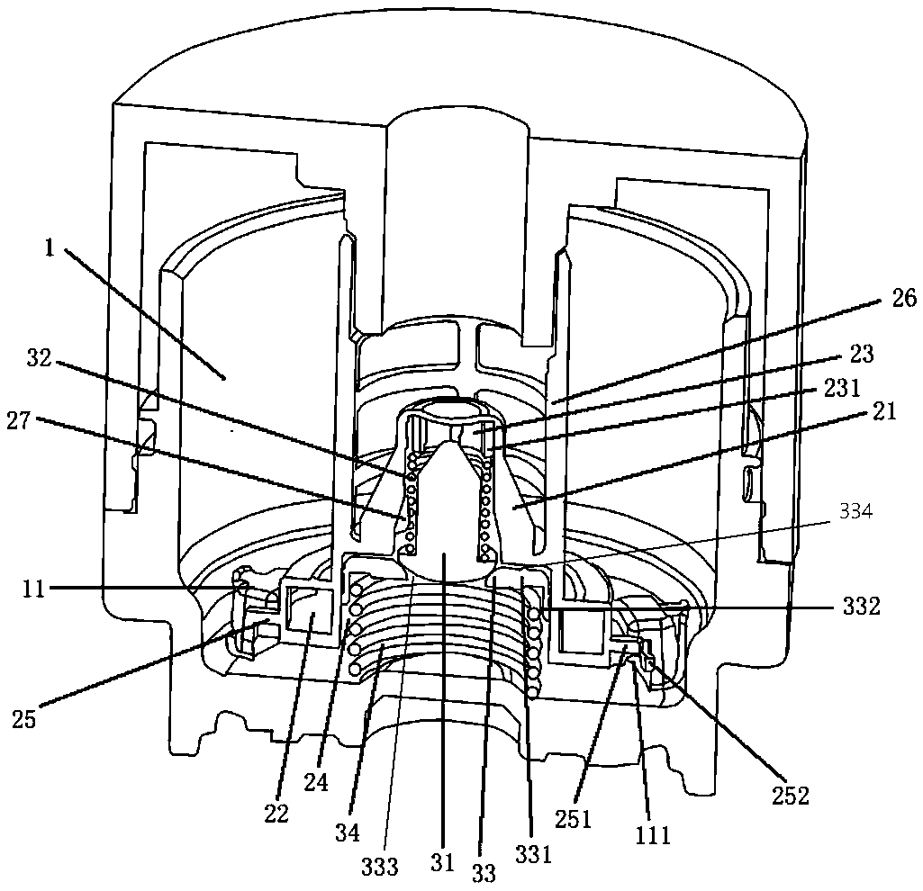
[0030] Such as figure 1 The installation structure of a new machine filter bypass valve shown includes an oil filter screw cover 1 and a bypass valve arranged inside the screw cover 1, and the screw cover 1 includes at least two connecting parts arranged circumferentially around its axis 11. The bypass valve includes a housing and a bypass assembly, wherein the housing is a plastic housing integrally formed. The housing includes a valve housing 21 and a functional housing 22 located below the valve housing 21. The functional housing 22 has a large cross-sectional area The annular shell, thus can have good mechanical properties, the valve shell 21 has the first valve chamber 23 with the opening downward, and the first valve chamber 23 is provided with two opposite support ridges 231 circumferentially spaced on its wall surface , the bypass assembly is located inside the valve housing 21; the valve housing 21 is combined with the inner wall of the functional housing 22 to form a...

Embodiment 2

[0035] The technical solution described in this embodiment is similar to that of Embodiment 1, the difference is that there are multiple connecting parts 11 , and the openings of the opening slots 111 have the same rotation direction. When the bypass valve is installed in this embodiment, the installation part 25 is snapped into the connection part 11 in order to put it vertically and then turn it, which is suitable for the situation where the installation space is small.


PUM


Abstract

The invention relates to a novel oil filter by-pass valve mounting structure and relates to the field of oil filters. The novel oil filter by-pass valve mounting structure comprises an oil filter spiral cover and a by-pass valve arranged on the inner side of the spiral cover, wherein the oil filter spiral cover comprises at least two connecting parts arranged in the circumferential direction of the axis of the spiral cover; the by-pass valve comprises a shell and a by-pass assembly; the shell comprises a valve shell and a functional shell below the valve shell; the valve shell is provided witha first valve chamber, and the opening of the valve chamber is downwards; a plurality of support ridges are arranged on the wall face of the first valve chamber at intervals in the circumferential direction and in the first valve chamber; the by-pass assembly is arranged in the valve shell; the valve shell and the inner wall of the functional shell are combined to form a second valve chamber; anda mounting part corresponding to and detachably connected with a connecting part is arranged in the circumferential direction of the functional shell. The novel oil filter by-pass valve mounting structure is detachably connected onto the oil filter spiral cover, so that the mounting structure does not need to be discarded along with a filter element; in addition, the novel oil filter by-pass valve mounting structure has high processing convenience and maintaining convenience; and moreover, the novel oil filter by-pass valve mounting structure has high working performance. The novel oil filterby-pass valve mounting structure has the advantages of being high in structural integrity and processing convenience, convenient to detach, mount and maintain and high in machine oil leakproofness.

Description

technical field [0001] The invention relates to the field of engine oil filters, in particular to a novel machine filter bypass valve installation structure. Background technique [0002] The bypass valve used in the oil filter is used when the filter element in the oil filter is blocked, the oil inlet and outlet of the filter reach a certain pressure difference, the bypass valve is opened, and the oil is not filtered. It flows directly into the lubricating main oil passage, thus ensuring the normal lubrication of the entire engine. [0003] As described in the Chinese invention patent with the publication number CN2037030577U, a bypass valve for an oil filter is built in the filter paper, and the bypass valve includes a central pipe and a bypass valve end cover. The input end of the central pipe mentioned above is closely connected with the filter paper through the end cover of the bypass valve. The center of the end cover of the bypass valve is provided with an oil inlet....

Claims


Application Information

Patent Timeline
Patent Type & Authority Applications(China)
IPC IPC(8): F01M11/03
CPCF01M11/03F01M2011/031
Inventor 程建彬张宇邓青林
Owner ZHEJIANG WEITAI AUTOMOBILE PARTS
Why Eureka
Try Eureka