
Working device of engine waste gas power turbine driving water pump

A technology for power turbines and working devices, which is applied in the direction of engine cooling, pump devices, engine components, etc., can solve problems such as engine power loss, achieve the effect of avoiding leakage problems, and the control structure is simple and stable

Inactive Publication Date: 2018-11-06
CHANGSHU INSTITUTE OF TECHNOLOGY
View PDF5 Cites 3 Cited by
  • Summary
  • Abstract
  • Description
  • Claims
  • Application Information

AI Technical Summary

Problems solved by technology

[0003] The purpose of the present invention is to provide a working device for engine exhaust gas power turbine driven water pump, to solve the problem of engine power loss caused by the water pump in the existing cooling system

Method used


Image

  • Working device of engine waste gas power turbine driving water pump
  • Working device of engine waste gas power turbine driving water pump
  • Working device of engine waste gas power turbine driving water pump

Examples


Embodiment Construction

[0015] The present invention will be further described below in conjunction with the examples, but not as a limitation of the present invention.

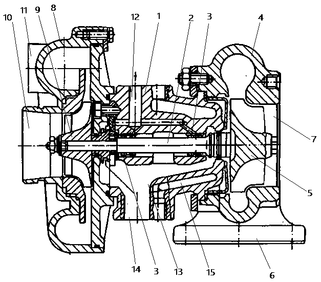
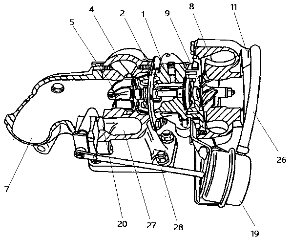
[0016] Please combine figure 1 ,to image 3 As shown, the working device of the engine exhaust gas power turbine driving the water pump includes a radial power turbine 1a, a centrifugal water pump 1b and an installation body 1. The installation body 1 is fixed between the radial power turbine 1a and the centrifugal water pump 1b, and the common shaft 2 passes through two floating The bearing 3 is supported in the mounting body 1 . The radial power turbine 1a includes a volute 4, a turbine impeller 5, a circumferential air inlet 6 and an axial exhaust port 7, and the volute 4 is provided with a circumferential air inlet 6 and an axial exhaust port 7 to guide exhaust gas evenly into the radial power The turbine 1a is also introduced into the exhaust manifold, which is cast with heat-resistant alloy cast iron and has a smooth inner s...


PUM


Abstract

The invention discloses a working device of an engine waste gas power turbine driving water pump. The working device comprises a runoff power turbine, a centrifugal water pump and a common shaft; therunoff power turbine comprises a volute, a turbine impeller, a peripheral intake port and an axial exhaust port; the centrifugal water pump comprises a shell, a water pump impeller, an axial water inlet and a peripheral water outlet; the turbine impeller and the water pump impeller are arranged at the two ends of the common shaft; the axial exhaust port and the axial water inlet are oppositely arranged; the volute is fixedly connected with the shell through a mounting body; and the common shaft is supported by the mounting body. The device changes a driving mode of the centrifugal water pump without influencing a cooling path of a traditional cooling system and without influencing the engine power.

Description

technical field [0001] The invention relates to a working device for driving a water pump, in particular to a working device for driving a water pump driven by an engine exhaust gas power turbine, and belongs to the technical field of automobile energy saving. Background technique [0002] In the total heat of the engine fuel, only 25% to 40% of the heat is converted into effective work, and the remaining 60% to 75% are lost. Among them, it is mainly taken away by the exhaust gas, and secondly passed to the coolant; the heat taken away by the coolant accounts for 10% to 35% of the total heat, and the heat taken away by the exhaust gas accounts for 25% to 50% of the total heat. Utilization of waste energy has always been a hot topic in the research of engine energy saving; looking at the research on the utilization of engine waste heat at home and abroad, it can be divided into two ways: using exhaust waste heat and using waste heat in engine coolant in terms of heat source u...

Claims


Application Information

Patent Timeline
Patent Type & Authority Applications(China)
IPC IPC(8): F01P5/12F04D13/04F01D15/08F01D17/10F01D17/20
Inventor 范炳良吕正兵赵飞
Owner CHANGSHU INSTITUTE OF TECHNOLOGY
Features
  • Generate Ideas
  • Intellectual Property
  • Life Sciences
  • Materials
  • Tech Scout
  • Unparalleled Data Quality
  • Higher Quality Content
  • 60% Fewer Hallucinations
Learn More