Tensioning mechanism suitable for automatic equipment

A technology of automation equipment and tensioning mechanism, which is applied in the direction of mechanical equipment, connecting components, transmission devices, etc., can solve the problems of inability to perform fine-tuning operations, loose and fixed bolts, and inconvenient use of bolt rotation adjustment, etc., to achieve tension Mechanism fine-tuning to solve the effect of loose and loose bolts

Inactive Publication Date: 2018-11-06
ANHUI HUAHUA BRIDGE EQUIP CO LTD
View PDF6 Cites 1 Cited by
  • Summary
  • Abstract
  • Description
  • Claims
  • Application Information

AI Technical Summary

Problems solved by technology

[0003] The purpose of the present invention is to provide a tensioning mechanism suitable for automation equipment to solve the above-mentioned background technology. Due to the vibration of the machine, the tensioning mechanism of the existing automation equipment in the above background technology will cause the bolts to be loosened and not firmly fixed due to machine vibration. , When adjusting the tension mechanism, it is inconvenient to use the bolt rotation adjustment, and the fine-tuning operation cannot be performed when the adjustment is urgently needed

Method used


Image

  • Tensioning mechanism suitable for automatic equipment
  • Tensioning mechanism suitable for automatic equipment
  • Tensioning mechanism suitable for automatic equipment

Examples


Embodiment Construction

[0017] The following will clearly and completely describe the technical solutions in the embodiments of the present invention with reference to the accompanying drawings in the embodiments of the present invention. Obviously, the described embodiments are only some, not all, embodiments of the present invention. Based on the embodiments of the present invention, all other embodiments obtained by persons of ordinary skill in the art without making creative efforts belong to the protection scope of the present invention.

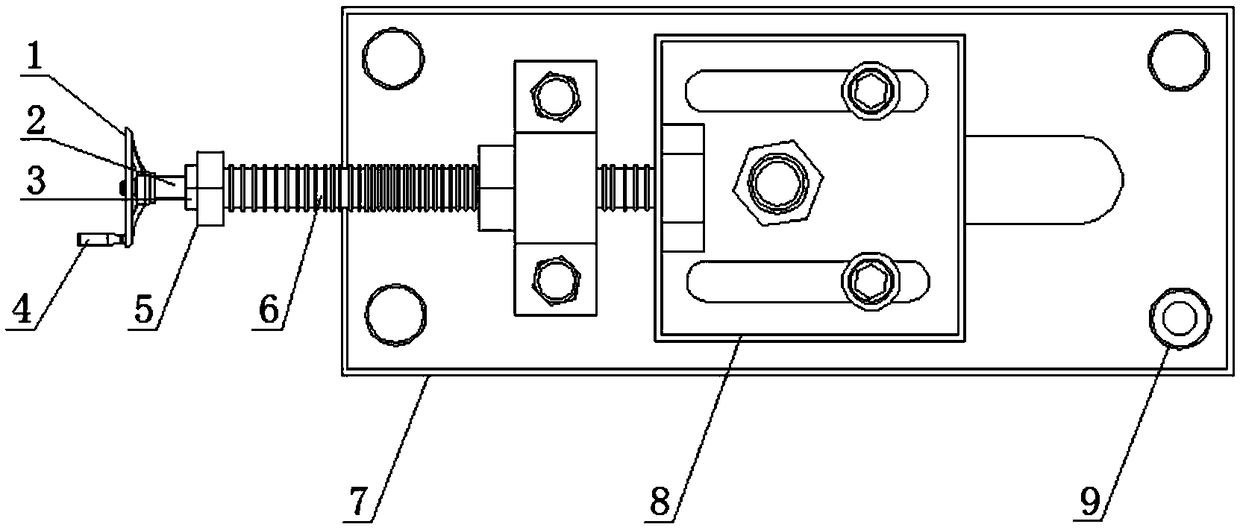
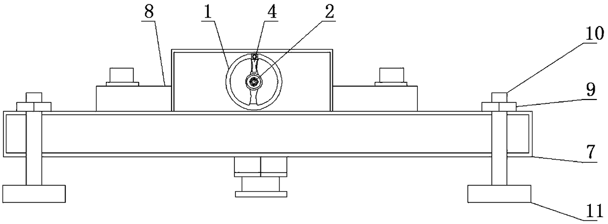
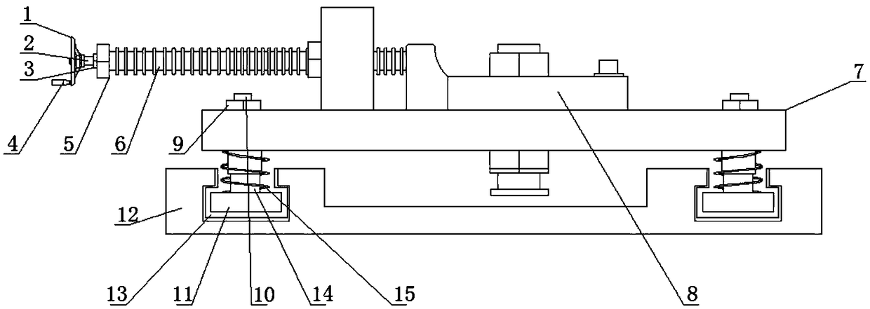
[0018] see figure 1 , figure 2 , image 3 and Figure 4 , the present invention provides a technical solution for a tensioning mechanism suitable for automation equipment: a tensioning mechanism suitable for automation equipment, including a tensioning mechanism fixing plate 7, and a slide is provided at the middle position of the upper surface of the tensioning mechanism fixing plate 7 Plate 8, one side of the sliding plate 8 is provided with a screw rod ...


PUM


Abstract

The invention discloses a tensioning mechanism suitable for automatic equipment. The tensioning mechanism suitable for the automatic equipment comprises a tensioning mechanism fixing plate; a slidingplate is arranged in the middle position of the upper surface of the tensioning mechanism fixing plate; a screw rod is arranged on one side of the sliding plate; a second nut is arranged on the outersurface of one end of the screw rod; a hand wheel connecting rod is arranged inside one end of the screw rod; and a first nut is arranged at one end of the hand wheel connecting rod, and a hand wheelis arranged at the other end of the hand wheel connecting rod. As a telescopic column and a spring are designed on the outer surface of one end of a clamping block connecting rod, the situation that abolt is loosened and not firmly fixed when directly used for fixing due to machine vibration in the using process of the tensioning mechanism suitable for the automatic equipment is avoided; by arranging the telescopic column and the spring in the surface of one end of the clamping block connecting rod in a sleeved mode, the tensioning mechanism fixing plate and a fixed bottom plate are connectedthrough clamping fit of a clamping block and a clamping groove, and at the moment, a third nut is screwed so that the tensioning mechanism fixing plate and the fixed bottom plate are firmer under action of the telescopic column and the spring.

Description

technical field [0001] The invention belongs to the technical field of automation equipment, and in particular relates to a tensioning mechanism suitable for automation equipment. Background technique [0002] The existing tensioning mechanism is an indispensable device when operating on automation equipment. In order to help the operator to operate and reduce manual operations during operation, but the tensioning mechanism of the existing automation equipment is directly damaged due to machine vibration during use. Fixing with bolts will make the bolts loose and unstable. When adjusting the tensioning mechanism, it is inconvenient to use the bolt rotation adjustment, and it is impossible to perform fine-tuning operations when adjustments are urgently needed. Therefore, we propose a tensioning mechanism suitable for automation equipment. tight body. Contents of the invention [0003] The purpose of the present invention is to provide a tensioning mechanism suitable for au...

Claims


Application Information

Patent Timeline
Patent Type & Authority Applications(China)
IPC IPC(8): F16B39/22F16H7/08
CPCF16B39/22F16H7/08
Inventor 黄小华
Owner ANHUI HUAHUA BRIDGE EQUIP CO LTD
Why Eureka
Try Eureka