A fastening bracket fastening rotary fin heat exchanger

A technology for fixing brackets and heat exchangers, which is applied to heat exchange equipment, heat exchanger shells, evaporators/condensers, etc. Insufficient fixation with the spiral finned tube, low bracket installation efficiency, etc., to achieve the effect of improving input cost and processing efficiency, not easy to loosen, and reducing material cost

Active Publication Date: 2017-12-01
HENAN NEW KELONG ELECTRICAL APPLIANCES
View PDF2 Cites 0 Cited by
  • Summary
  • Abstract
  • Description
  • Claims
  • Application Information

AI Technical Summary

Problems solved by technology

[0004] However, the above-mentioned invention patents have the following problems: 1. Since the support for fixing the spiral fin pipeline needs to be bent into a "semi-cylindrical part", the processing of the support requires many stamping processes, the investment in stamping dies is too large, and manual stamping is required A good sheet is bent in a semi-cylindrical shape, and the processing is time-consuming and laborious; 2. "The semi-cylindrical part is extruded by an extrusion device so as to fit tightly on the outer surface of the spiral fin tube", the spiral fin mentioned here The outer surface of the tube refers to the outer surface of "the corrugated belt having a predetermined width and spirally wound on the tube through which the fluid flows", where the installation efficiency of the bracket is low, and the semi-cylindrical part of the bracket is incompatible with the spiral finned tube The fixation is not tight and easy to loosen; 3. "The semi-cylindrical part has a part extending parallel to both sides" and the semi-cylindrical part is squeezed and fixed on the fold belt of the spiral fin pipeline by the extrusion device, which is not conducive to Heat dissipation; the above problems seriously affect the processing cost, efficiency, product quality and heat dissipation effect of this type of heat exchanger, and urgently need to be solved

Method used


Image

  • A fastening bracket fastening rotary fin heat exchanger
  • A fastening bracket fastening rotary fin heat exchanger
  • A fastening bracket fastening rotary fin heat exchanger

Examples


Embodiment Construction

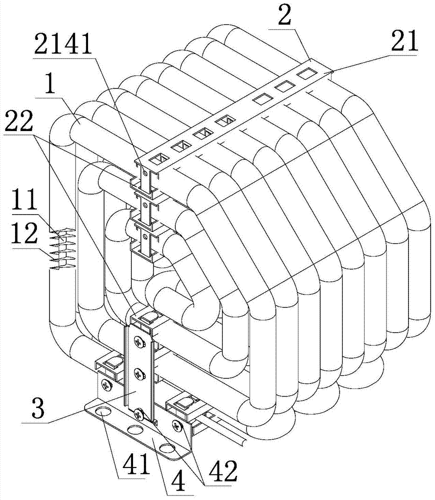
[0020] see Figure 1-Figure 4 As shown, a fastening bracket fastening rotary fin heat exchanger, which includes a spiral finned tube 1 with a coiled layer structure, seven sets of spiral finned tube plane fixing frames 2, a plane fixing frame connecting plate 3 and a bottom fixing plate 4, The spiral-finned tube 1 of the roll layer structure includes a condenser tube 11 and a spiral fin 12 spirally wound outside the condenser tube 11;

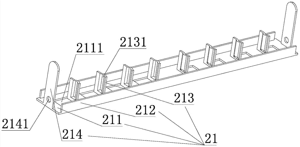
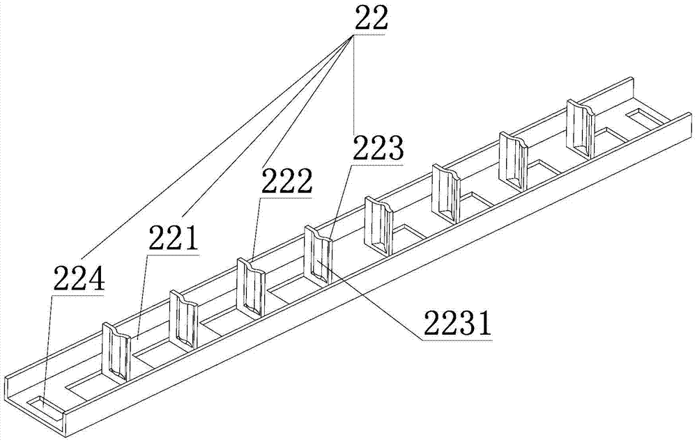
[0021] Said each set of spiral finned tube plane fixtures 2 includes a small bracket 21 and a small bracket cover plate 22; the small bracket 21 and the small bracket cover plate 22 are arranged in a direction perpendicular to the pipeline direction of the spiral finned tube, and the roll layer structure The spiral finned tube whose upper part is in the same plane is sandwiched between a group of small brackets 21 and the small bracket cover plate 22, and the small brackets 21 and the small bracket cover plate 22 are inserted and fixed, and the...


PUM


Abstract

The invention relates to a fixed bracket snap-fit ​​rotary fin heat exchanger, which comprises a coiled layer structure spiral finned tube, at least two sets of spiral finned tube plane fixing frames clamped outside the spiral finned tube, and the plane fixing frame connecting The plate and the bottom fixing plate, the spiral finned tubes on the upper part of the spiral finned tube are connected and fixed by the plane fixing frame connecting plate at the end of the spiral finned tube plane fixing frame; the bottom of the spiral finned tube is in the same plane. The finned tubes are clamped in two sets of spiral finned tube plane fixing frames arranged in parallel. The ends of the same side of the two sets of spiral finned tube plane fixing frames are screwed with the bottom fixing plate through screws, and each bottom fixing plate is connected to the lower part. The ends of the plane fixing frame of the spiral finned tube corresponding to each layer of the spiral finned tube are connected and fixed to each other through the connecting plate of the plane fixing frame; the parts of the invention have simple structure, convenient processing, low cost, and fast and efficient assembly between parts , The components are firmly fixed and not easy to loosen.

Description

technical field [0001] The invention relates to a rotary-fin heat exchanger, in particular to a fixed-bracket snap-fit ​​rotary-fin heat exchanger. Background technique [0002] At present, with the development of refrigeration industries such as refrigerators, rotary fin heat exchangers have gradually been applied in the field of refrigeration. [0003] Chinese patent application number 200610111866.5, application date August 29, 2006, authorized announcement date: December 31, 2008, authorized announcement number CN100447505C, discloses a "spiral fin condenser", a spiral fin condenser, including Helically finned tube formed by a corrugated strip having a predetermined width and helically wound on a tube through which fluid flows, characterized in that the helically finned tube is first bent into a serpentine shape for horizontal arrangement by horizontal fixtures and fixed, and then secondarily bent in the longitudinal direction of the serpentine of the first bend, wherei...

Claims


Application Information

Patent Timeline
Patent Type & Authority Patents(China)
IPC IPC(8): F25B39/00
CPCF28F1/36F28F9/013
Inventor 高相启程清丰张金法柴建新申成兵张平平梁开王东铖
Owner HENAN NEW KELONG ELECTRICAL APPLIANCES
Why Eureka
Try Eureka