Three-degree-of-freedom turning frame system applied to dynamic flight simulator of helicopter

A dynamic flight and simulator technology, which is applied to the simulation devices, simulators, instruments and other directions of space navigation conditions, can solve the problems of difficult positioning of the shaft connection coaxial, limited motor driving torque, and difficult disassembly and assembly of the rotating frame system, etc. Achieve the effect of increasing structural integrity and reliability, increasing structural strength and rigidity, and reducing mass and moment of inertia

Active Publication Date: 2018-11-06
GENERAL ENG RES INST CHINA ACAD OF ENG PHYSICS
View PDF22 Cites 16 Cited by
  • Summary
  • Abstract
  • Description
  • Claims
  • Application Information

AI Technical Summary

Problems solved by technology

[0007] 2. In the centrifugal field environment, the rotating frame of the prior art cannot overcome the huge overturning force and centrifugal force under the centrifugal field, and overcome the problem of limited driving torque of the motor
[0008] 3. In the prior art, it is difficult to disassemble and assemble the multi-degree-of-freedom rotating frame system
[0009] 4. In the prior art, it is difficult to connect the shafting to the same axis, and there is also the problem of over-positioning
[0010] 5. In the existing technology, there is a static balance problem in the rotating frame

Method used


Image

  • Three-degree-of-freedom turning frame system applied to dynamic flight simulator of helicopter
  • Three-degree-of-freedom turning frame system applied to dynamic flight simulator of helicopter
  • Three-degree-of-freedom turning frame system applied to dynamic flight simulator of helicopter

Examples


Embodiment 1

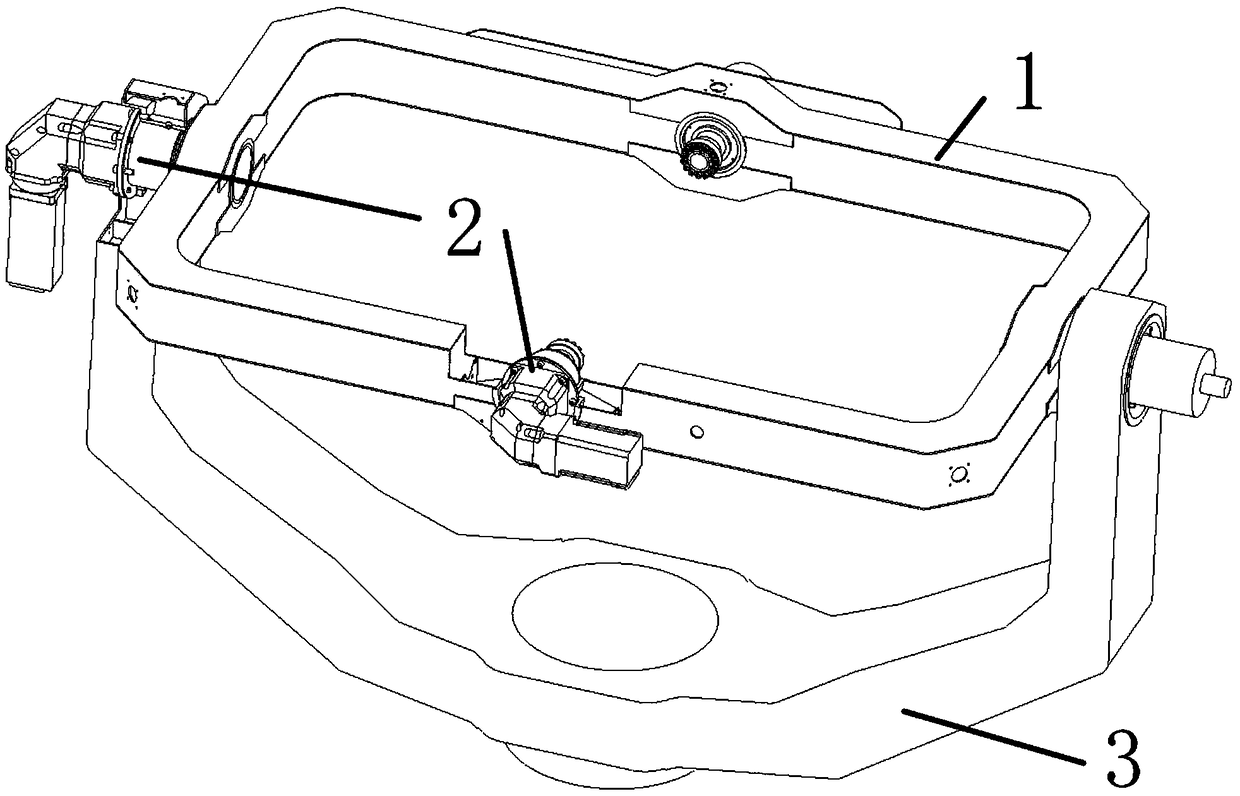
[0055] Example 1, such as figure 1 Shown:

[0056] Three degrees of freedom rotating frame system for helicopter dynamic flight simulator, including:

[0057] Rolling frame 1; the manned cockpit (not shown) is rotatably mounted on the rolling frame 1;

[0058] The yaw frame 3; the roll frame 1 is rotatably mounted on the yaw frame 3, and the yaw frame 3 is rotatably mounted on the arm of the centrifuge platform; the rotation plane of the manned cockpit is perpendicular to the rotation plane of the roll frame 1, The rotation plane of the yaw frame 3 is perpendicular to the rotation plane of the manned cockpit and the rotation plane of the roll frame 1 respectively.

[0059] The roll frame 1 is rotatably connected to the manned cockpit to realize the pitching motion of the manned cockpit, the yaw frame 3 is rotatably connected to the roll frame 1 to realize the roll motion of the manned cockpit, and the yaw frame 3 is connected to the end of the rotating arm of the centrifuge T...

Embodiment 2

[0060] Example 2, such as figure 1 with figure 2 Shown:

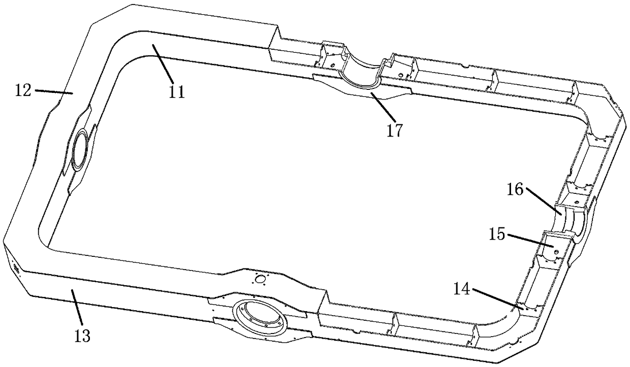
[0061] The difference between this embodiment and Embodiment 1 is that the rolling frame 1 is a rectangular frame structure, and the rolling frame 1 includes:

[0062] Rectangular inner ring plate 11;

[0063] A rectangular outer ring plate 13; the outer ring plate 13 is installed outside the inner ring plate 11;

[0064] Two cover plates 12; the two cover plates 12 are respectively arranged on the upper and lower parts after the combination of the inner ring plate 11 and the outer ring plate 13, and surround a rectangular hollow structure, and each side of the rectangular hollow structure is provided with a shaft hole 16 , the two shaft holes 16 on the opposite sides are coaxial. The shaft hole 16 on each side of the rectangular hollow structure is located at the center of each side. Preferably, on the rolling frame 1, at the position where the shaft hole 16 is provided, the inner ring plate 11 and the outer ring...

Embodiment 3

[0066] Example 3, such as figure 2 Shown:

[0067] The difference between this embodiment and embodiment 2 is that the rolling frame 1 also includes:

[0068] A plurality of ribs 14; the plurality of ribs 14 are vertically installed inside the rectangular hollow structure at even intervals, and the four sides of each rib 14 are respectively fixedly connected to the inner ring plate 11, the outer ring plate 13 and the two cover plates 12;

[0069] A plurality of ribs 15; the ribs 15 are installed inside the rectangular hollow structure on both sides of the shaft hole 16, and the four sides of the ribs 15 are respectively fixedly connected to the inner ring plate 11, the outer ring plate 13, a rib 14 and the wall of the shaft hole 16.

[0070] The design of the ribs 14 and the ribs 15 only increases the structural strength and rigidity of the roll frame 1 with a small weight, and at the same time increases the structural integrity and reliability. The design of the rib plate ...


PUM


Abstract

The invention discloses a three-degree-of-freedom turning frame system applied to a dynamic flight simulator of a helicopter. A rolling and turning frame is connected with a manned cabin in a rotatable manner to realize pitching motion of the manned cabin; a yawing frame is connected with the rolling and turning frame in a rotatable manner to realize rolling and turning motion of the manned cabin;the yawing frame is connected with the tail end of a turning arm of a centrifugal machine through a bearing to realize yawing motion of the manned cabin, so that the manned cabin rotates in three degrees of freedom in a centrifugal field; the rolling and turning frame and the manned cabin as well as the rolling and turning frame and the yawing frame are respectively connected through expansion sleeves; furthermore, a power system is mounted on a shaft sleeve; the shaft sleeve is mounted in a shaft hole. The structural cooperation is relatively easy to mount and dismount; due to the design ofa round table structure on a pin shaft and a conical surface in the shaft hole, the pin shaft can be automatically guided and located during mounting, and the cooperation precision is high.

Description

technical field [0001] The invention belongs to the technical field of helicopter dynamic flight simulation, and in particular relates to a three-degree-of-freedom rotating frame system used for a helicopter dynamic flight simulator. Background technique [0002] The three-degree-of-freedom rotating frame system of the helicopter dynamic flight simulator is installed at the end of the rotating arm of the centrifuge platform, which can realize arbitrary attitude changes in space in a continuous overload environment, and is used for flight simulation training, especially flight illusion training. Flying illusion, that is, the pilot cannot correctly perceive the position, movement and attitude of the aircraft or himself, and it is easy to cause wrong operation and lead to flight accidents. In order to reduce the illusion of flight, an effective method is to simulate through a ground simulator to improve the pilot's cognition and achieve the purpose of overcoming the illusion of...

Claims


Application Information

Patent Timeline
Patent Type & Authority Applications(China)
IPC IPC(8): G09B9/12
CPCG09B9/12
Inventor 何阳蒋春梅宋琼黎启胜赵世鹏陈磊白俊林胡荣华尹鹏
Owner GENERAL ENG RES INST CHINA ACAD OF ENG PHYSICS
Why Eureka
Try Eureka