
Compensation data transmission method and display panel

A technology of compensation data and transmission method, which is applied to static indicators, instruments, etc., and can solve the problems of slow writing speed of compensation data and low transmission efficiency

Active Publication Date: 2018-11-06
KUNSHAN GO VISIONOX OPTO ELECTRONICS CO LTD
View PDF9 Cites 3 Cited by
  • Summary
  • Abstract
  • Description
  • Claims
  • Application Information

AI Technical Summary

Problems solved by technology

[0004] Based on this, it is necessary to provide a compensation data transmission method and a display pa

Method used


Image

  • Compensation data transmission method and display panel
  • Compensation data transmission method and display panel
  • Compensation data transmission method and display panel

Examples


Embodiment Construction

[0070] In order to make the purpose, technical solution and advantages of the present application clearer, the present application will be further described in detail below in conjunction with the accompanying drawings and embodiments. It should be understood that the specific embodiments described here are only used to explain the present application, and are not intended to limit the present application.

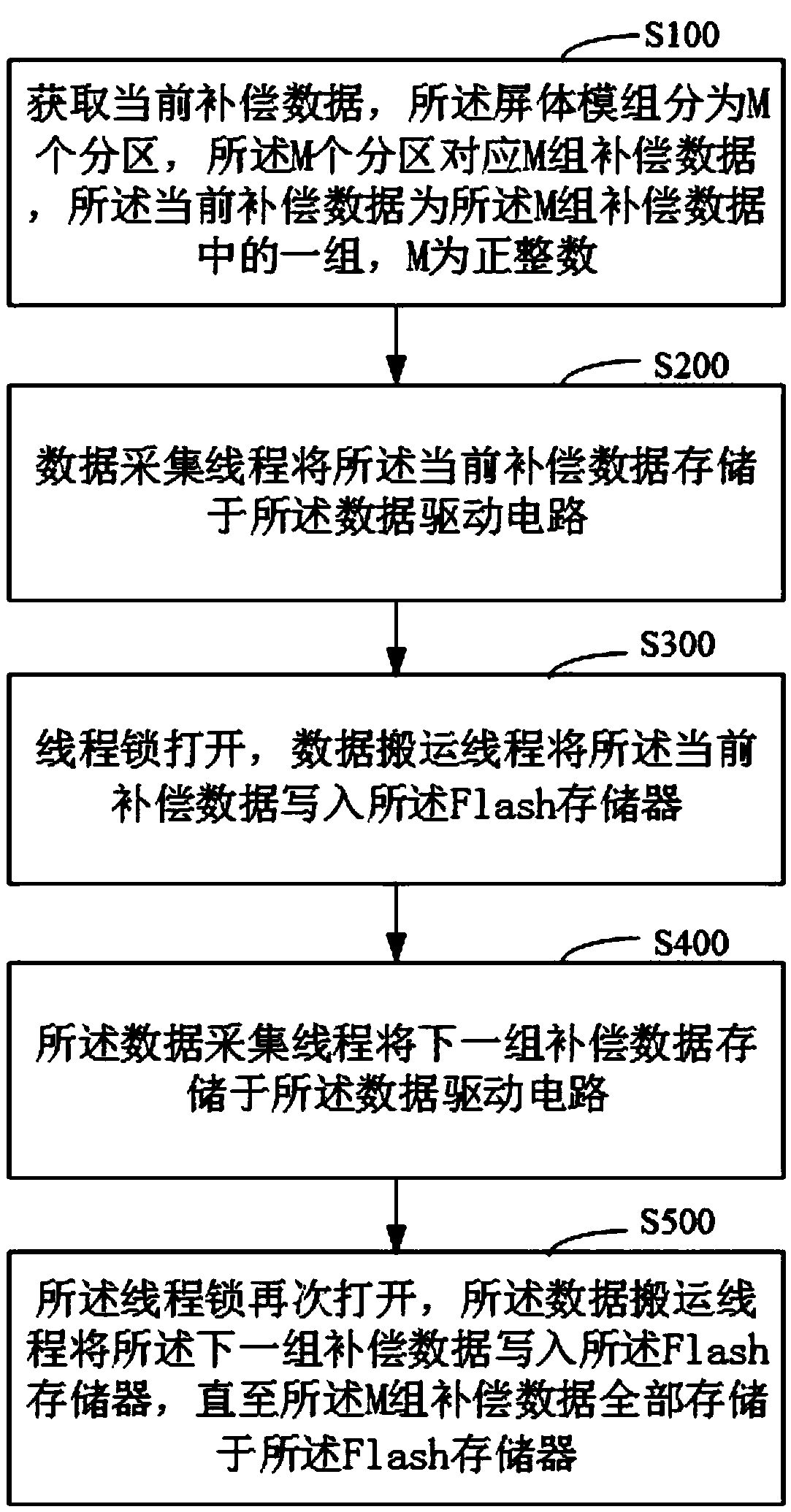
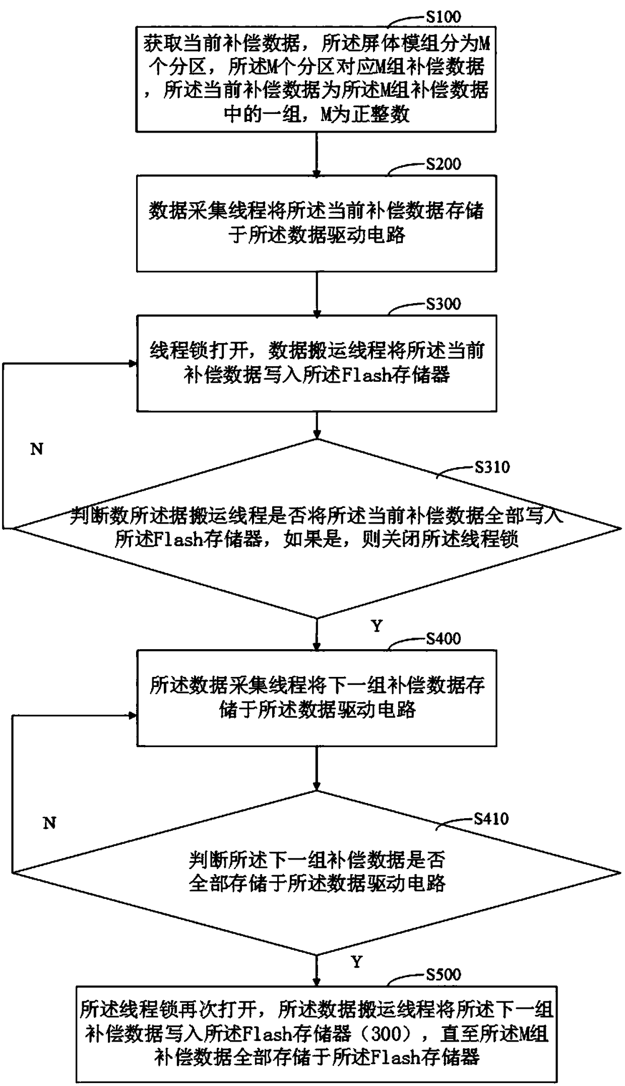
[0071] see figure 1 and image 3 , in one embodiment, a compensation data transmission method is provided, which is used to realize the transmission of the compensation data of the display panel 10 .

[0072] The display panel 10 may include a screen module 100 , a data driving circuit 200 and a Flash memory 300 . The data driving circuit 200 is electrically connected to the screen module 100 and the Flash memory 300 respectively. The screen module 100 includes a base and arrayed pixel units arranged on the surface of the base. The data driving circuit 200 is used to t...


PUM


Abstract

The present invention relates to a compensation data transmission method and a display panel. The method comprises the steps of: obtaining current compensation data; storing the current compensation data into a data drive circuit through a data collection thread, opening a thread lock, and writing the current compensation data into a Flash storage through a data carrying thread; and storing the next group of compensation data into the data drive circuit through the data collection thread; opening the thread again, and writing the next group of compensation data into the Flash storage through the data carrying thread until M groups of compensation data are all stored in the Flash storage. The method allow the transmission paths of the M groups of compensation data to be simple and executesoperations of storage of the next group of compensation data into the data drive circuit and writing-in of the current compensation data to the Flash storage at the same time so as to save the transmission time of the M groups of compensation data and improve the transmission efficiency and the transmission accuracy of the M groups of compensation data.

Description

technical field [0001] The present application relates to the field of display technology, in particular to a compensation data transmission method and a display panel. Background technique [0002] At present, Active Matrix Driving OLED (AMOLED for short) has the advantages of self-illumination, high display contrast, thin thickness, wide viewing angle, fast response speed, wide operating temperature range, simple structure and manufacturing process, etc. properties are widely used. However, the current of the organic light-emitting diode will vary with the shift of the threshold voltage of the driving transistor, so that the AMOLED display panel will have non-uniform display brightness Mura (color spot defect). The Mura phenomenon means that the actual brightness of some pixels is darker or brighter than the theoretical brightness that should be displayed, thereby affecting the brightness uniformity and brightness constancy of the AMOLED display panel. [0003] At presen...

Claims


Application Information

Patent Timeline
IPC IPC(8): G09G3/3225
CPCG09G3/3225G09G2320/0233
Inventor 李志明
Owner KUNSHAN GO VISIONOX OPTO ELECTRONICS CO LTD
Learn More