
Novel cable bridge

A cable bridge and bridge technology, applied in the direction of electrical components, etc., can solve problems such as not simple enough, cumbersome steps, and no major breakthroughs in functions, and achieve the effect of avoiding overheating damage

Pending Publication Date: 2018-11-06
JIANGSU JINLI ELECTRIC
View PDF1 Cites 4 Cited by
  • Summary
  • Abstract
  • Description
  • Claims
  • Application Information

AI Technical Summary

Problems solved by technology

[0003] A Chinese patent discloses a cable tray with isolation grooves (authorized announcement number CN207039112U). This patented technology can set isolation grooves and can clearly classify and install cables. However, the steps of this patent are cumbersome and not simple enough. no major breakthrough

Method used


Image

  • Novel cable bridge
  • Novel cable bridge
  • Novel cable bridge

Examples


Embodiment Construction

[0021] In order to make the content of the present invention more clearly understood, the present invention will be further described in detail below based on the specific embodiments and in conjunction with the accompanying drawings.

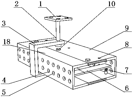
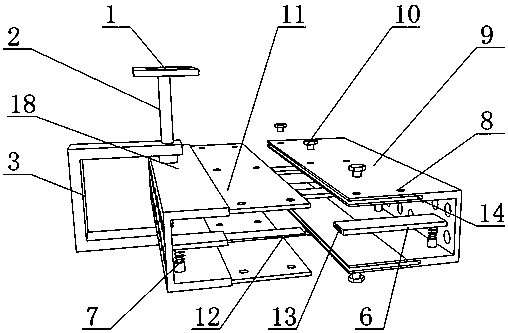
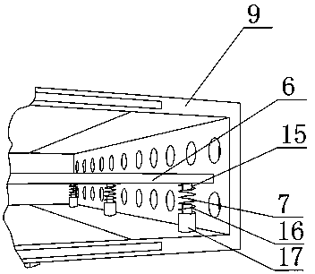
[0022] see Figure 1~3 , in the embodiment of the present invention, a new type of cable tray includes a fixed plate 1, a bracket 3, a right bridge 9, and a left bridge 18, the lower surface of the fixed plate 1 is provided with a connecting rod 2, and the bottom end of the connecting rod 2 is equipped with a bracket 3. A left bridge 18 is installed on the left side of the inner side of the bracket 3, and a right bridge 9 is installed on the right side of the left bridge 18, and the outside of the right bridge 9 and the left bridge 18 are provided with cooling holes 4, and the external setting of the cooling holes 4 Anti-ash net 5 is arranged, and the inside of right bridge frame 9 is provided with clamping plate 6, and the right side of left b...


PUM


Abstract

The invention discloses a novel cable bridge. The novel cable bridge comprises a fixed plate, a bracket, a right bridge and a left bridge; a connecting rod is arranged at the lower surface, the bracket is arranged at the bottom end of the connecting rod, the left bridge is arranged at the inner side, close to the left location, of the bracket, the right bridge is arranged at the right side of theleft bridge, and radiating holes are formed on the outsides of the right bridge and the left bridge; a dustproof screen is arranged at the external of the radiating holes, a clamping plate is arrangedin the right bridge, a first spile is arranged at the right side of the left bridge, and a first slot is arranged at the left side of the right bridge. The radiating holes arranged on the cable bridge can be used for radiating the cable, thereby preventing the cable from overheat damaging; the dustproof screen is provided for preventing the dust from entering into the bridge through the radiatingholes and interfering the radiating of the cable; the first spile is inserted into the first slot and fixedly connected with a bolt hole through a bolt, the width of the cable bridge is changed, andmore cables can be accommodated.

Description

technical field [0001] The invention relates to the technical field of cable trays, in particular to a novel cable tray. Background technique [0002] Cable trays are divided into trough type, tray type, ladder type, grid type and other structures, and are composed of brackets, supporting arms and installation accessories. The bridge frame in the building can be erected independently or attached to various buildings (structures) and pipe gallery supports. It should reflect the characteristics of simple structure, beautiful appearance, flexible configuration and convenient maintenance. All parts need to be galvanized. , installed in the open-air bridge outside the building. [0003] A Chinese patent discloses a cable tray with isolation grooves (authorized announcement number CN207039112U). This patented technology can set isolation grooves and can clearly classify and install cables. However, the steps of this patent are cumbersome and not simple enough. No major breakthro...

Claims


Application Information

Patent Timeline
IPC IPC(8): H02G3/04H02G3/03
CPCH02G3/03H02G3/045
Inventor 顾纪阳
Owner JIANGSU JINLI ELECTRIC
Learn More