
Bus device and electrical control cabinet system

A technology for electrical control cabinets and control cabinets, which is applied in the installation of busbars, electrical components, and cables. It can solve the problems of large space occupation, loss or damage, and easy forgetting of busbars, and achieves convenient debugging and space-saving installation. small effect

Pending Publication Date: 2018-11-06
LUOYANG XINSILU ELECTRIC
View PDF0 Cites 0 Cited by
  • Summary
  • Abstract
  • Description
  • Claims
  • Application Information

AI Technical Summary

Problems solved by technology

[0005] The purpose of the present invention is to provide a busbar device to solve the technical problems existing in the prior art that the busbars of connected electrical cabinets occupy a large space during installation and the busbars are easily forgotten, lost or damaged during transportation
[0006] The purpose of the present invention is also to provide an electrical control cabinet system to solve the technical problems existing in the prior art that the connected electrical cabinet busbar takes up a lot of space during installation and the busbar is easily forgotten, lost or damaged during transportation

Method used


Image

  • Bus device and electrical control cabinet system
  • Bus device and electrical control cabinet system
  • Bus device and electrical control cabinet system

Examples


Embodiment 1

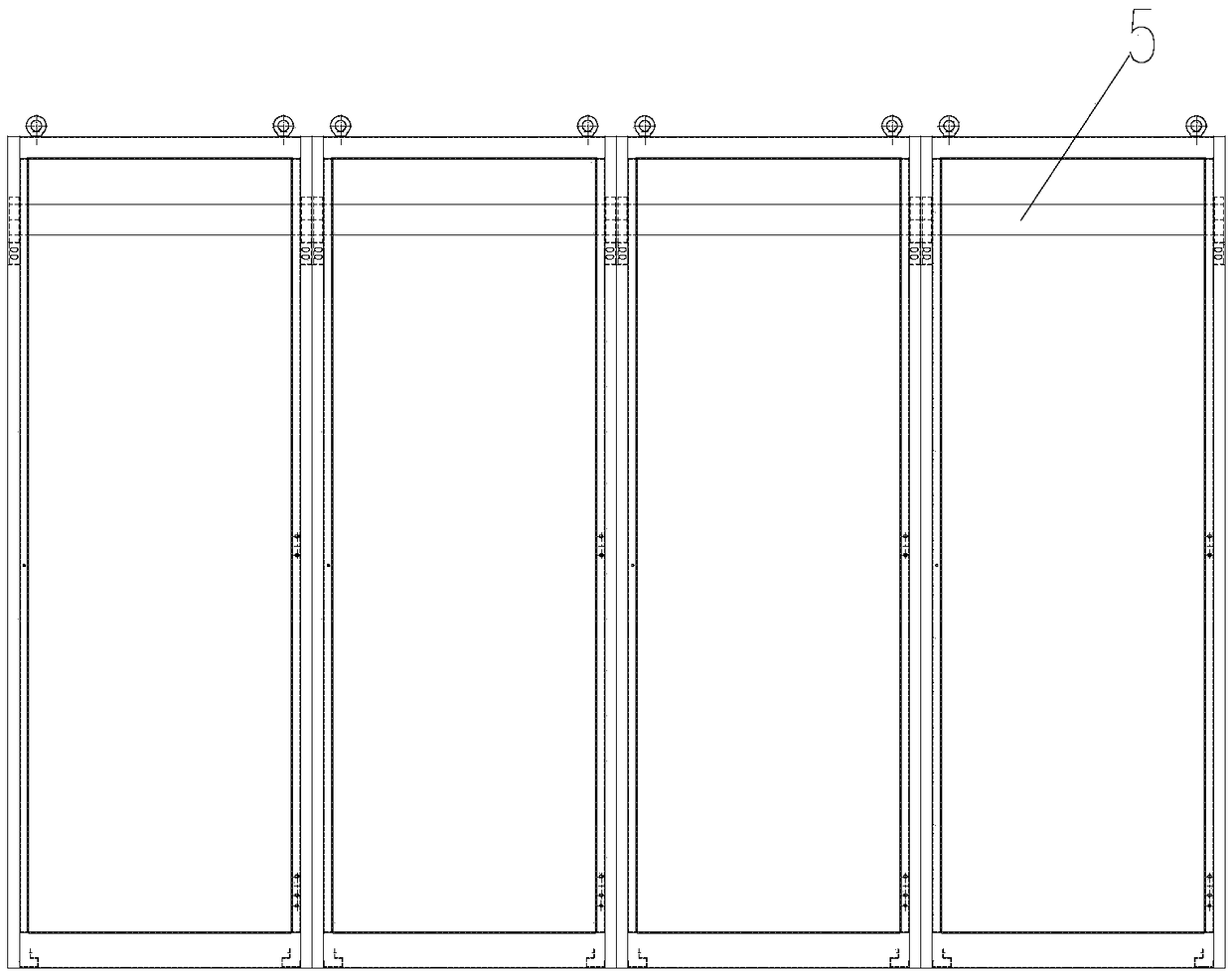
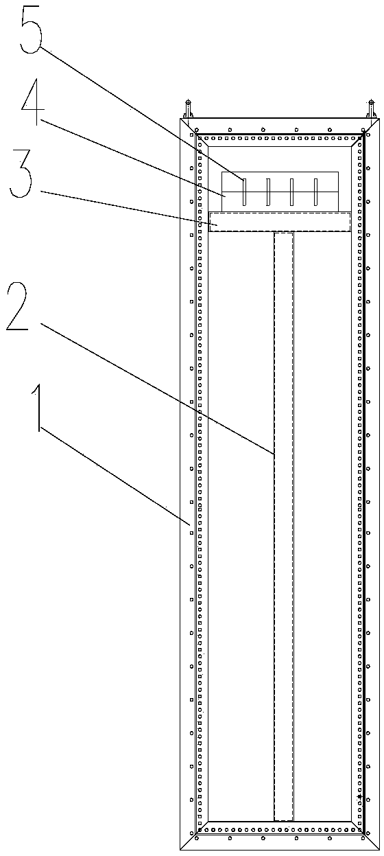
[0045] see Figure 5 to Figure 12As shown, this embodiment provides a busbar device, which is applied to a conjoined electrical cabinet, and the conjoined electrical cabinet is formed by connecting multiple electrical control cabinets.

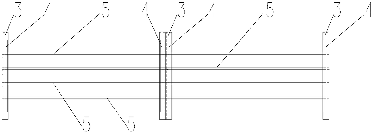
[0046] The bus bar device includes multiple bus bar units and multiple overlapping bars 7 . Wherein, each of the bus bar units is installed on an electrical control cabinet, and the bus bar unit includes at least one bus bar 5, and the plurality of bus bar units are arranged end to end in sequence, and the bus bar 5 on each bus bar unit The corresponding bus bars 5 on the adjacent bus bar units are connected through the overlapping bars 7 .

[0047] It can be understood that since each busbar unit is arranged on one side of the electrical control cabinet, "the plurality of busbar units are arranged end-to-end in sequence", that is, the multi-sided electrical control cabinets are arranged side by side in sequence, so as to correspond to the el...

Embodiment 2

[0064] This embodiment provides an electrical control cabinet system, including a multi-faceted electrical control cabinet, and the control cabinet frame 1 of the electrical control cabinet is provided with the busbar device described in the first embodiment.

[0065] Specifically, the control cabinet frames 1 for installing the busbars 5 are respectively arranged on the multi-faceted electrical control cabinets, and the control cabinet frames 1 of the multi-faceted electrical control cabinets are respectively installed with busbar units one by one, and the adjacent electrical control cabinets are set correspondingly. The busbars 5 are fixedly connected through the overlapping bars 7 .

[0066] Specifically, each control cabinet frame 1 is provided with the bus bar frame installation beam 6 , upright column 2 and bus bar frame 4 described in the first embodiment, so as to fix the bus bar unit.

[0067] The specific structure and principle of each component involved in this emb...


PUM


Abstract

The invention relates to the technical field of electrical control, and discloses a bus device and an electrical control cabinet system. The bus device comprises a plurality of bus bar units and a plurality of overlapping rows, wherein each bus bar unit is arranged on one electrical control cabinet; each bus bar unit comprises at least one bus bar; the plurality of bus bar units are arranged oppositely in sequence front head to end; and the bus bar on each bus bar unit is connected with corresponding bus bars on adjacent bus bar units through the overlapping rows. The bus device and the electrical control cabinet system can be mounted conveniently, easily and rapidly. Meanwhile, the efficiency can be increased; the production cost is lowered; and forgetting, loss and damage of the bus barsare avoided.

Description

technical field [0001] The invention relates to the technical field of electrical control, in particular to a bus device and an electrical control cabinet system. Background technique [0002] The electrical control cabinet is mainly used to control the electrical operation of the mechanical equipment on site, and at the same time adjust different operations according to different actions on site. Due to the complexity of on-site mechanical equipment, the number of electrical control cabinets is also different. Many mechanical equipment require multi-faceted electrical control cabinets for control, and these multi-faceted electrical control cabinets need to be connected together on site to form a whole (hereinafter referred to as "connection") Body electrical cabinet), in order to effectively control the mechanical equipment on site. [0003] A common power bus bar is installed above the conjoined cabinets, and each electrical control cabinet can take power from the upper p...

Claims


Application Information

Patent Timeline
Patent Type & Authority Applications(China)
IPC IPC(8): H02G5/00
CPCH02G5/00
Inventor 胡洛夷姚长莹张皓张永钢
Owner LUOYANG XINSILU ELECTRIC
Learn More