Unlock instant, AI-driven research and patent intelligence for your innovation.

Scheduling system active-standby switching method and device

A dispatching system and master/standby switching technology, applied in the direction of circuit devices, electrical components, etc., can solve problems such as a large number of workstations, messy dispatching desks, and increased workload of automation personnel

Inactive Publication Date: 2018-11-06
GUANGDONG POWER GRID CO LTD +1
View PDF2 Cites 1 Cited by
  • Summary
  • Abstract
  • Description
  • Claims
  • Application Information

AI Technical Summary

Problems solved by technology

[0003] 1. It is necessary to configure two main and standby workstations, which will increase investment and make the dispatching desk messy;
[0004] 2. Mis-scheduling is prone to occur, and the disk should be monitored on the main dispatching system, but may log in to the workstation of the standby dispatching system;
[0005] 3. The number of workstations is large, which increases the workload of automation personnel

Method used


Image

  • Scheduling system active-standby switching method and device
  • Scheduling system active-standby switching method and device
  • Scheduling system active-standby switching method and device

Examples


Embodiment 1

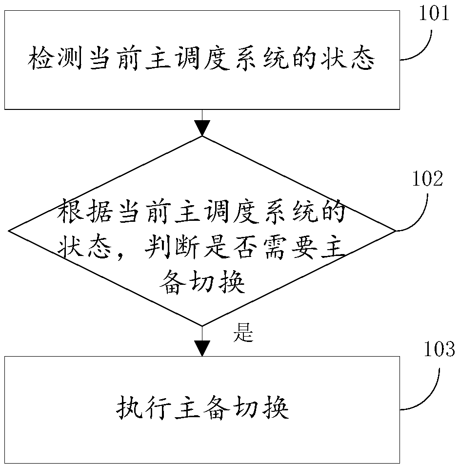
[0039] join figure 1 Shown is a flow chart of a method for master-standby switching of a dispatching system, the method is applied to specifically include the following steps:

[0040] S101. Detect the state of the current main dispatching system;

[0041] S102. According to the state of the current master dispatching system, it is judged whether master-standby switching is required;

[0042] If yes, execute step S103.

[0043] S103. Row master / standby switchover.

[0044] Among them, in the embodiment of the present invention, such as figure 2 As shown, the step 103 includes the following two steps:

[0045] S1031. Modify the identifier corresponding to the currently used system to the identifier of the backup dispatching system, and modify the environment variable of the system operating environment to a variable matching the backup dispatching system.

[0046] S1032. Transmit the operating parameters of the current main dispatching system to the backup dispatching sys...

Embodiment 2

[0049] join image 3 A flow chart of active-standby switchover of a dispatching system is shown, the method is implemented on the basis of the active-standby switchover of the dispatching system provided in Embodiment 1, and specifically includes the following steps:

[0050] S201. Detect the state of the current main dispatching system;

[0051] S202. According to the state of the current master dispatching system, determine whether master-standby switching is required;

[0052] If yes, execute step S203.

[0053] S203. Perform active / standby switchover.

[0054] S204. Monitor the state of the primary dispatching system, and transmit the monitored state of the primary dispatching system to the backup dispatching system.

[0055] S205. Collect abnormality information of the primary dispatching system, and transmit the abnormality information of the primary dispatching system to the backup dispatching system.

[0056] The embodiment of the present invention provides a metho...

Embodiment 3

[0058] Regarding the master / standby switching method of the dispatching system provided in the foregoing embodiments, the embodiment of the present invention provides a device for master / standby switching of the dispatching system, see Figure 4 Shown is a structural block diagram of a device for active / standby switching of a dispatching system, the device includes the following parts:


PUM


Abstract

The invention provides a scheduling system active-standby switching method and device. The method comprises the following steps: detecting a state of the current main scheduling system; judging whether the active-standby switching is required according to the state of the current main scheduling system; and executing the active-standby switching if the active-standby switching is required. Throughthe design provided by the invention, the scheduling system can be directly switched, an operation of preparing two work stations is unnecessary, and the problem of logging the work station in mistaken is reduced; the work station is reduced, so that the workload of the automation personnel is reduced.

Description

technical field [0001] The present invention relates to the technical field of electric power dispatching, in particular to a method and device for master-standby switching of a dispatching system. Background technique [0002] In the prior art, the main and standby scheduling automation systems each have their own workstations, and both the main and standby workstations need to be equipped with dispatchers. When the main dispatching system fails, the dispatcher needs to monitor the disk in the standby dispatching system. There are following problems in this design: [0003] 1. It is necessary to configure two workstations as the main and backup workstations, which will increase investment and make the dispatching desk messy; [0004] 2. Mis-scheduling is prone to occur, and the disk should be monitored on the main dispatching system, but may log in to the workstation of the standby dispatching system; [0005] 3. The large number of workstations increases the workload of ...

Claims


Application Information

Patent Timeline
IPC IPC(8): H02J13/00
CPCH02J13/00
Inventor 段孟雍吴钟飞李祺威刘沛林钟志明邓景柱鲁承波汪杰刘淑芬郑惠芳卫敬宜
Owner GUANGDONG POWER GRID CO LTD