
Dead-beat control system and method for permanent magnet synchronous motor with complex vector modeling in discrete domain

A permanent magnet synchronous motor, deadbeat control technology, applied in vector control system, control system, motor generator control and other directions, can solve problems such as poor control effect, small current control static error, and large current static error.

Active Publication Date: 2018-11-06
ZHUZHOU ELECTRIC LOCOMOTIVE CO +1
View PDF2 Cites 22 Cited by
  • Summary
  • Abstract
  • Description
  • Claims
  • Application Information

AI Technical Summary

Problems solved by technology

[0006] In order to solve the deficiencies in the prior art, the object of the present invention is to provide a permanent magnet synchronous motor deadbeat control system and method based on discrete domain complex vector modeling, which solves the problem of traditional permanent magnet synchronous motor deadbeat control systems at low switching frequencies. There are problems such as poor control effect, large current static difference, and large output torque pulsation. The deadbeat control strategy has a good control effect at low switching frequency, and the current control static difference is also small.

Method used


Image

  • Dead-beat control system and method for permanent magnet synchronous motor with complex vector modeling in discrete domain
  • Dead-beat control system and method for permanent magnet synchronous motor with complex vector modeling in discrete domain
  • Dead-beat control system and method for permanent magnet synchronous motor with complex vector modeling in discrete domain

Examples


Embodiment Construction

[0041] The present invention will be further described below in conjunction with the accompanying drawings. The following examples are only used to illustrate the technical solution of the present invention more clearly, but not to limit the protection scope of the present invention.

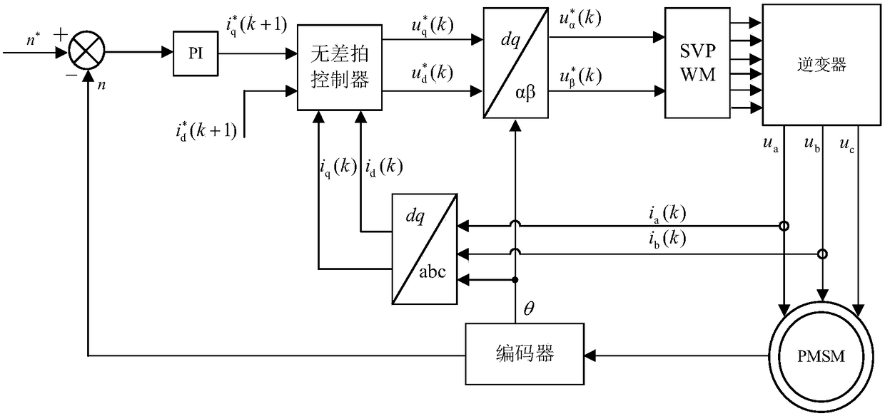
[0042] Such as figure 1 As shown, a permanent magnet synchronous motor deadbeat control system based on discrete domain complex vector modeling mainly includes: permanent magnet synchronous motor (PMSM), encoder, abc-dq coordinate conversion unit, speed outer loop PI controller, current Deadbeat controller, dq-αβ coordinate conversion unit, SVPWM modulation module, inverter. specifically:

[0043] The encoder is used to obtain the rotor position angle θ of the permanent magnet synchronous motor and the real-time speed n of the permanent magnet synchronous motor;

[0044] The abc-dq coordinate conversion unit collects the real-time current i of the AB phase of the stator of the permanent magne...


PUM


Abstract

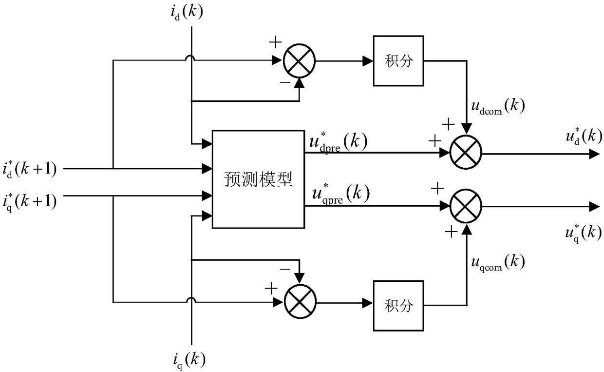
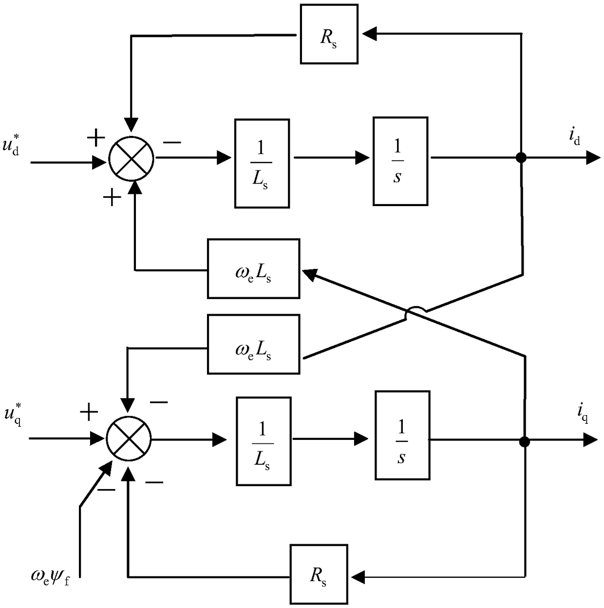
The invention discloses a dead-beat control system and a method for a permanent magnet synchronous motor with complex vector modeling in a discrete domain, which is characterized in that the system comprises a permanent magnet synchronous motor, an encoder, an abc-dq coordinate conversion unit, a speed outer loop PI controller, a current dead-beat controller, a dq-Alphabeta coordinate conversion unit, an SVPWM modulation module, and an inverter. The invention has the beneficial effects that: in the modeling process of the current prediction model, the inverter and the motor are regarded as a whole modeling, the delay action of the inverter is considered, and the established model is more accurate than the traditional current prediction model; a current error integral compensation module isadded to the dead-beat controller, the stator current control static error is greatly improved, and finally the purpose of no-beat control at low switching frequency is achieved. The results show that the motor speed and stator current are well controlled, the motor stator current control static error is small, and the output torque ripple is also improved.

Description

technical field [0001] The invention relates to a permanent magnet synchronous motor deadbeat control system and method based on discrete domain complex vector modeling, and belongs to the technical field of motor control. Background technique [0002] Permanent magnet synchronous traction motors for rail transit generally have a large power of hundreds of kilowatts. Due to the limitation of switching losses, in reality, an inverter with a low switching frequency of about 500 Hz has to be used to control the drive motor. [0003] At present, permanent magnet synchronous motors generally use dual-PI vector control strategies, but at low switching frequencies, the system sampling delay will be greatly increased, which will destroy the dynamic decoupling in the vector control system, and the motor control is difficult to meet the control requirements, and the output stator The current contains a large number of harmonics, which makes the output torque of the motor fluctuate gre...

Claims


Application Information

Patent Timeline
Patent Type & Authority Applications(China)
IPC IPC(8): H02P21/00H02P21/18H02P21/22H02P6/10
CPCH02P6/10H02P21/0017H02P21/18H02P21/22
Inventor 王颖杰曾伟肖黎亚焦岚轶张栋时阳廖国强王亚娟秦超沈伟
Owner ZHUZHOU ELECTRIC LOCOMOTIVE CO
Learn More