Lateral-moving screening and jigging machine

A jig and dynamic screen technology, applied in the field of jig equipment, can solve the problems of equipment adjustment and maintenance difficulties, poor adaptability of mineral particles, etc.

Inactive Publication Date: 2018-11-09
江西金石宝矿山机械制造有限公司
View PDF0 Cites 3 Cited by
  • Summary
  • Abstract
  • Description
  • Claims
  • Application Information

AI Technical Summary

Problems solved by technology

Since the traditional side diaphragm power jig is composed of a fixed box tank and a sieve plate, the water impulse and suction generated by the reciprocating motion of the rubber film driven by the ecce

Method used


Image

  • Lateral-moving screening and jigging machine
  • Lateral-moving screening and jigging machine

Examples


Embodiment Construction

[0012] The following will clearly and completely describe the technical solutions in the embodiments of the present invention with reference to the accompanying drawings in the embodiments of the present invention. Obviously, the described embodiments are only some, not all, embodiments of the present invention. Based on the embodiments of the present invention, all other embodiments obtained by persons of ordinary skill in the art without making creative efforts belong to the protection scope of the present invention.

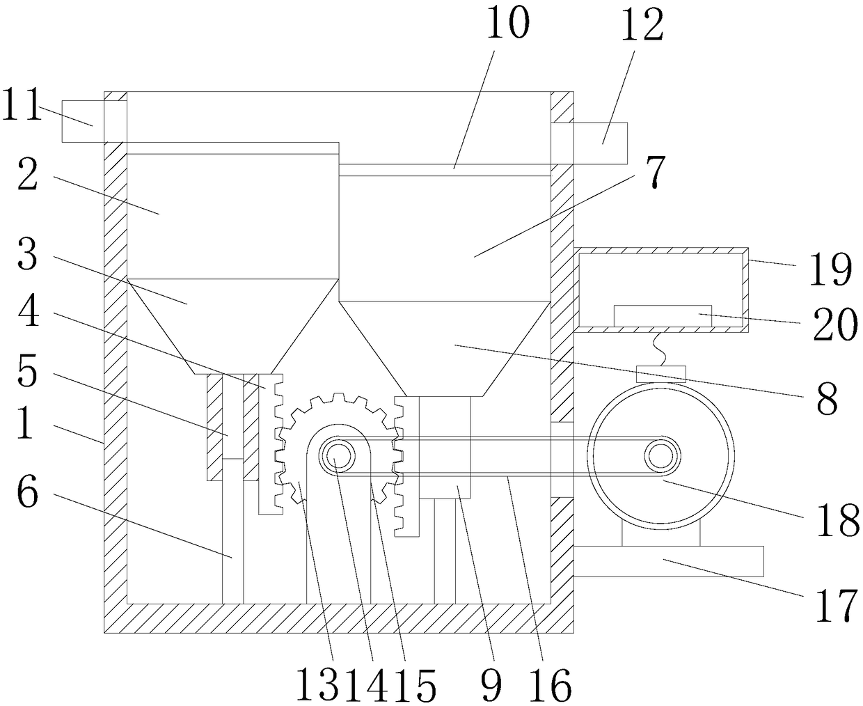
[0013] see Figure 1-2 , the present invention provides a technical solution: a side-moving screening jig, including a box body 1, a bracket 15 is installed on the inner bottom of the box body 1, a rotating shaft 14 is movably connected to the bracket 15, and a gear is installed on the rotating shaft 14 13. Cylinders 6 are installed symmetrically on both sides of the bracket 15, the first cylinder 5 is slidably socketed on the cylinder 6 on the left side of th...


PUM


Abstract

The invention discloses a lateral-moving screening and jigging machine, comprising a box body. A support frame is installed at the bottom of the interior of the box body, a rotating shaft is movably connected to the support frame, a gear is installed on the rotating shaft, and cylinder columns are separately and symmetrically installed on the two sides of the support frame. A first cylinder is slidably connected on the cylinder column positioned on the left side of the support frame in a sleeving mode, a second cylinder is slidably connected on the cylinder column positioned on the right sideof the support frame in a sleeving mode, the top end of the first cylinder is fixedly welded at the center position of the bottom end of a first discharge hopper, a first feed hopper is welded at thetop end of the first discharge hopper in a penetrating mode, the top end of the second cylinder is fixedly welded at the center position of the bottom end of a second discharge hopper, and a second feed hopper is welded at the top end of the second discharge hopper in a penetrating mode. Screening plates are separately installed at the top end opening positions of the first feed hopper and the second feed hopper, a feed inlet is formed in the top of the left side wall of the box body, and a discharge outlet is formed in the top of the right side wall of the box body. The screening and jiggingmachine is compact in structure and convenient to use.

Description

technical field [0001] The invention relates to the field of jig equipment, in particular to a side-moving screening jig. Background technique [0002] The jig used for gravity beneficiation can be divided into dozens of types according to the transmission mode, the position of the diaphragm, the motion characteristics of the pulsating water flow, the shape of the sorting tank, and the way of ore discharge. Currently, it is widely used in the beneficiation production of metal mines. The main applications are lower diaphragm power jig and side diaphragm power jig. Since the traditional side diaphragm power jig is composed of a fixed box tank and a sieve plate, the water impulse and suction generated by the reciprocating motion of the rubber film driven by the eccentric wheel push the mineral particles in the medium water. Therefore, the traditional side The power jig has poor adaptability to mineral particles, and it is difficult to adjust and maintain the equipment. Conte...

Claims


Application Information

Patent Timeline
IPC IPC(8): B03B5/18B03B5/24
CPCB03B5/18B03B5/24
Inventor 黄小明黄佩
Owner 江西金石宝矿山机械制造有限公司
Why Eureka
Try Eureka