Cap for movement guide device
一种运动引导、导轨的技术,应用在直线运动的轴承、抗离心力的转动部件、轴承等方向,能够解决盖向导轨固定固定力减弱等问题
- Summary
- Abstract
- Description
- Claims
- Application Information
AI Technical Summary
Problems solved by technology
Method used
Image
Examples
no. 1 approach
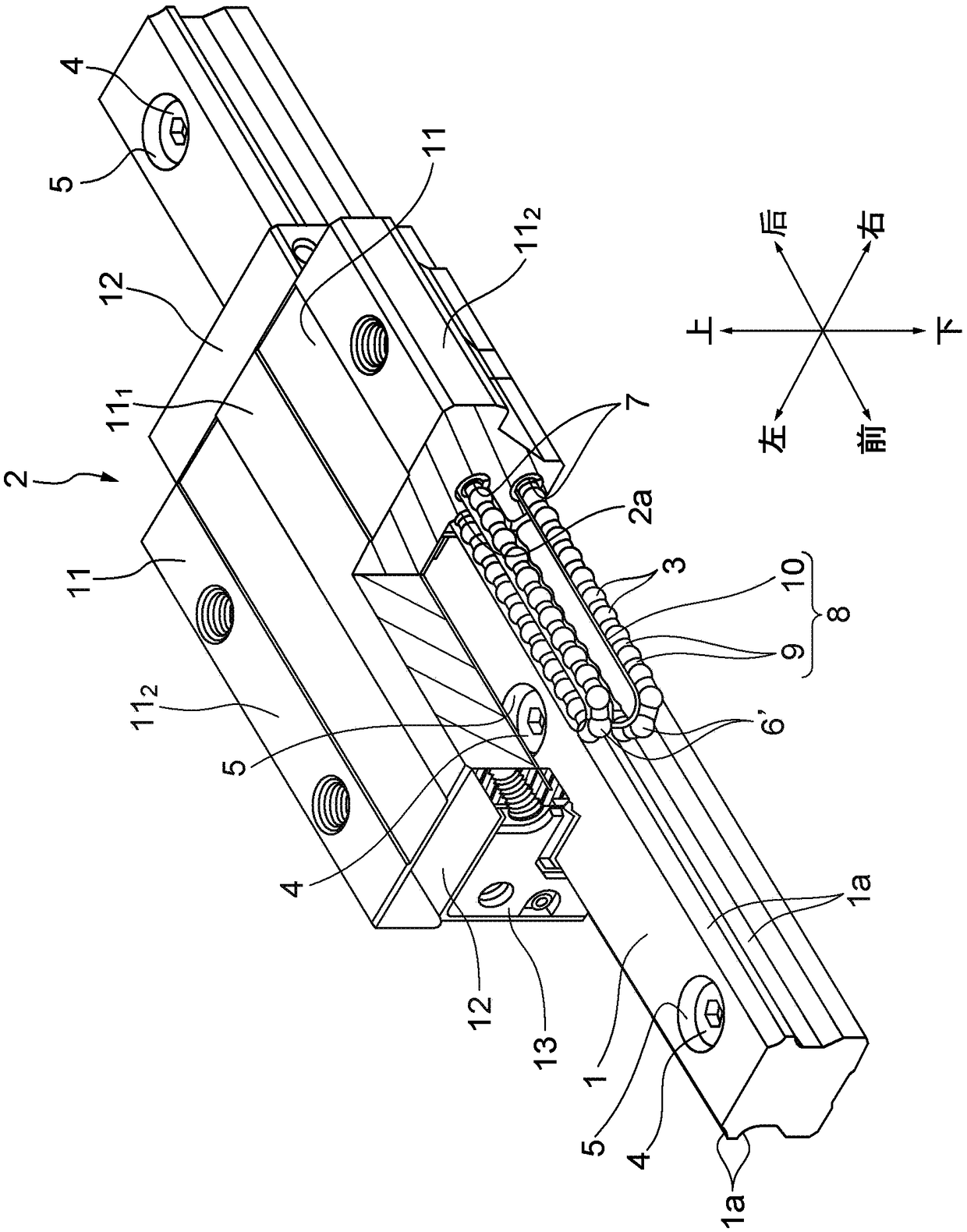
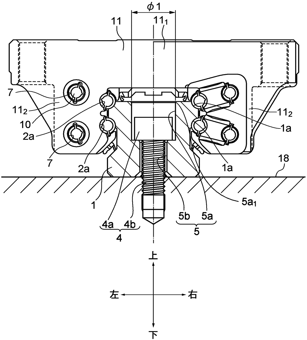
[0031] The structure of the motion guide that is knocked into the cover is shown below. figure 1 represents a perspective view of a motion guiding device, figure 2 Front view showing the motion guide with the end plate removed. The motion guide device includes: a guide rail 1 linearly extending in the longitudinal direction; and a carriage 2 assembled to the guide rail 1 so as to be linearly movable in the longitudinal direction via a plurality of rolling elements 3 such as balls and rollers. It should be noted that, below, the guide rail 1 is installed on a horizontal plane, and the direction when the guide rail 1 is viewed from the longitudinal direction, that is, figure 1 , figure 2 The structure of the motion guide device will be described with reference to the up-down, left-right, and front-rear directions, but the arrangement of the motion guide device is not limited thereto. In addition, in the drawings, the same reference numerals are attached to the same componen...
no. 2 approach
[0060] Figure 10 It is a bottom view showing the lid 31 of the second embodiment of the present invention, Figure 11 express Figure 10 X-X line sectional view. The cover 31 of the second embodiment also includes: a disc-shaped upper surface portion 22 ; a cylindrical side surface portion 23 hanging from the upper surface portion 22 ; and a plurality of protrusions 24 provided on the outer peripheral surface of the side surface portion 23 . The upper surface portion 22 has a thick central portion 22a and a peripheral portion 22b thinner than the central portion 22a. A flange 27 is provided on the periphery of the upper surface portion 22 . A plurality of protrusions 24 (six protrusions 24 in this embodiment) are provided at equal intervals in the circumferential direction on the outer peripheral surface of the side surface portion 23 . Similar to the first embodiment, the protrusion 24 exists in the region from the upper end portion to the axially intermediate portion of...
no. 3 approach
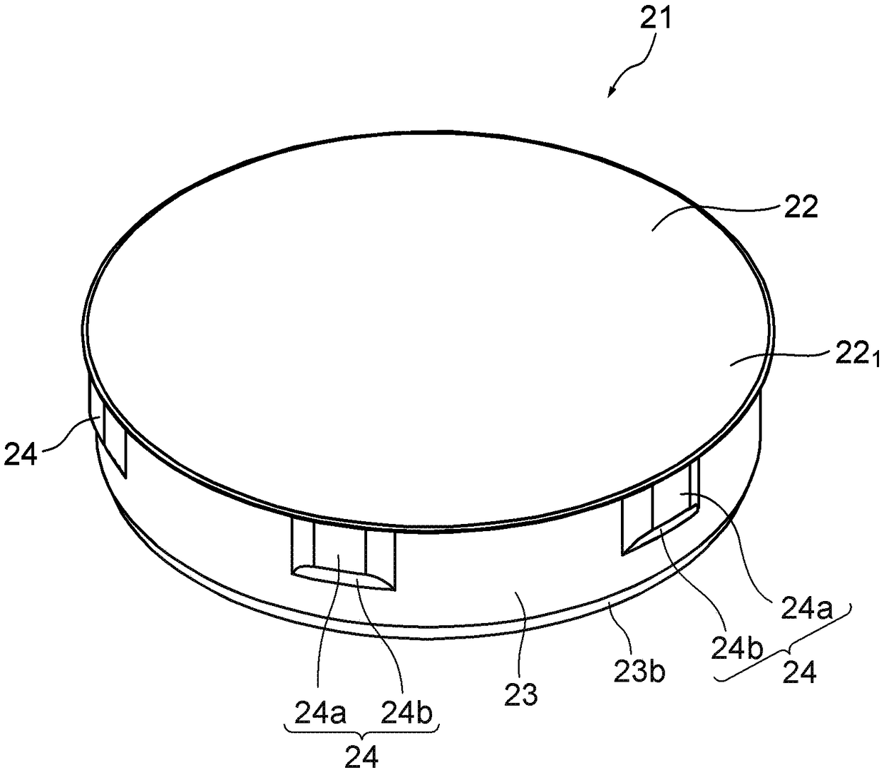
[0069] Figure 12 A perspective view showing the upper surface side of the cover 41 of the third embodiment, Figure 13 A bottom perspective view of the cover 41 is shown. The cover 41 also includes: a disc-shaped upper surface portion 22 ; a cylindrical side surface portion 23 hanging down from the upper surface portion 22 ; and a plurality of protrusions 24 provided on the outer peripheral surface of the side surface portion 23 .
[0070] Figure 14 shows a bottom view of the cover 41, Figure 15 express Figure 14 XIV-XIV line sectional view. In this cover 41 , the area (height×width) of the protrusion 24 is made larger than that of the cover 21 of the first embodiment and the cover 31 of the second embodiment in order to further increase the pulling force and holding force. The protrusion 24 exists in the region from the upper end portion to the axially intermediate portion of the outer peripheral surface 23 a of the side surface portion 23 . From the upper surface 2...
PUM
 Abstract
Description
Claims
Application Information
 - R&D
- Intellectual Property
- Life Sciences
- Materials
- Tech Scout
- Unparalleled Data Quality
- Higher Quality Content
- 60% Fewer Hallucinations
Browse by: Latest US Patents, China's latest patents, Technical Efficacy Thesaurus, Application Domain, Technology Topic, Popular Technical Reports.
© 2025 PatSnap. All rights reserved.Legal|Privacy policy|Modern Slavery Act Transparency Statement|Sitemap|About US| Contact US: help@patsnap.com


