
Water tank structure and cleaning robot

A technology for cleaning robots and water tanks, applied in the field of intelligent robots, can solve the problems of poor integration and high cost of water tanks, and achieve the effects of low cost, simple control, and simple overall structure

Active Publication Date: 2018-11-13
AMICRO SEMICON CORP
View PDF15 Cites 6 Cited by
  • Summary
  • Abstract
  • Description
  • Claims
  • Application Information

AI Technical Summary

Problems solved by technology

Because these control methods need to use solenoid valves, the cost is relatively high, and the connection between the solenoid valve and the vent hole is connected by a hose, resulting in poor integration of the water tank

Method used


Image

  • Water tank structure and cleaning robot
  • Water tank structure and cleaning robot
  • Water tank structure and cleaning robot

Examples


Embodiment Construction

[0023] The technical solutions in the embodiments of the present invention will be described in detail below with reference to the drawings in the embodiments of the present invention. It should be understood that the specific embodiments described below are only used to explain the present invention, not to limit the present invention. In the following description, specific details are given to provide a thorough understanding of the embodiments. However, one of ordinary skill in the art would understand that the embodiments may be practiced without these specific details. For example, circuits may be shown in block diagrams in order not to obscure the embodiments in unnecessary detail. In other instances, well-known circuits, structures and techniques have not been shown in detail in order not to obscure the embodiments.

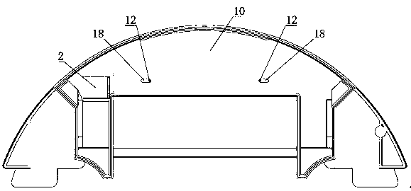
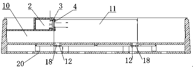
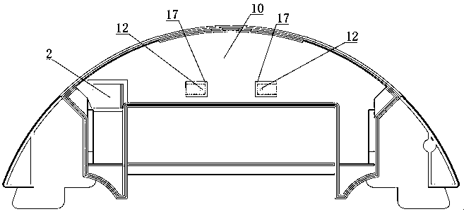
[0024] Such as figure 1 with 2 , or as in image 3 with 4 A water tank structure is shown, and the water tank structure is applied in a cleaning rob...


PUM


Abstract

The invention relates to a water tank structure and a cleaning robot. According to the water tank structure, on-off control of an air inlet hole is realized by arranging an air stop component formed by a fixed catch and a movable separation blade in the air inlet hole and controlling the rotation of the movable separation blade by a driving motor, the integral structure is simple, the cost is relatively low, and the control is very simple. In addition, the cleaning robot of the water tank structure is arranged, and the action of the driving motor is controlled by a control module, so as to control the on-off of the air inlet hole of the water tank main body, and further control the water outlet condition of the water tank main body, and therefore, the intelligence and practicability of thecleaning robot are improved.

Description

technical field [0001] The invention relates to the field of intelligent robots, in particular to a water tank structure and a cleaning robot. Background technique [0002] Existing cleaning robots can walk and move autonomously, so cleaning robots can also be called mobile robots. In addition to the function of sweeping and vacuuming, the cleaning robot generally also has the function of mopping the floor, so these cleaning robots are usually equipped with a water tank structure. When the robot is mopping the floor, the water in the water tank structure will normally flow out into the cleaning cloth to keep the cleaning cloth moist and improve the mopping effect. A Chinese utility model patent with the announcement number CN207084779U discloses a water tank structure of a sweeper. By setting a pumping mechanism between the main body of the water tank and the main body, the control unit of the intelligent sweeper is used to control the pumping mechanism to the main body of ...

Claims


Application Information

Patent Timeline
Patent Type & Authority Applications(China)
IPC IPC(8): A47L11/28A47L11/40
CPCA47L11/28A47L11/40A47L11/4011A47L11/4083
Inventor 肖刚军
Owner AMICRO SEMICON CORP
Learn More