Line electrode workpiece different-speed compound motion micro electrolytic line cutting machining method

A technology of cutting processing and compound motion, which is applied in the direction of electric processing equipment, metal processing equipment, manufacturing tools, etc., can solve the problems of increasing mass transfer capacity, poor quality, short circuit of processing, etc., and achieves the improvement of efficiency and stability, and the conductivity Uniform distribution and improved mass transfer efficiency

Active Publication Date: 2018-11-13
NANJING UNIV OF AERONAUTICS & ASTRONAUTICS
View PDF5 Cites 3 Cited by
  • Summary
  • Abstract
  • Description
  • Claims
  • Application Information

AI Technical Summary

Problems solved by technology

Researchers have proposed methods such as axial micro-amplitude vibration of the wire electrode, circular wire travel of the wire electrode, and low-frequency vibration of piezoelectric ceramics. Since the wire electrode is a cylindrical metal wire with a smooth outer surface at the micron level, its ability to drag and disturb is limited. The discharge effect of the product in the wide ratio structure is weak, resulting in a short circuit in the processing, and the processing cannot be carried out stably. Therefore, the ability of the wire electrode to vibrate slightly in the axial direction and the ring wire of the wire electrode to increase mass transfer is not good, and the low frequency vibration of piezoelectric ceramics is to a certain extent The flow field in the processing gap has been improved, but there are still problems of processing products and air bubbles adhering to the electrode wire and the surface of the workpiece
In addition, the researchers proposed a method of radial reciprocating vibration of the wire electrode to improve mass transfer, but this method is only suitable for simple linear structures, and it is difficult to realize the radial reciprocating vibration of the wire electrode when processing complex trajectories.

Method used


Image

  • Line electrode workpiece different-speed compound motion micro electrolytic line cutting machining method
  • Line electrode workpiece different-speed compound motion micro electrolytic line cutting machining method
  • Line electrode workpiece different-speed compound motion micro electrolytic line cutting machining method

Examples


Embodiment Construction

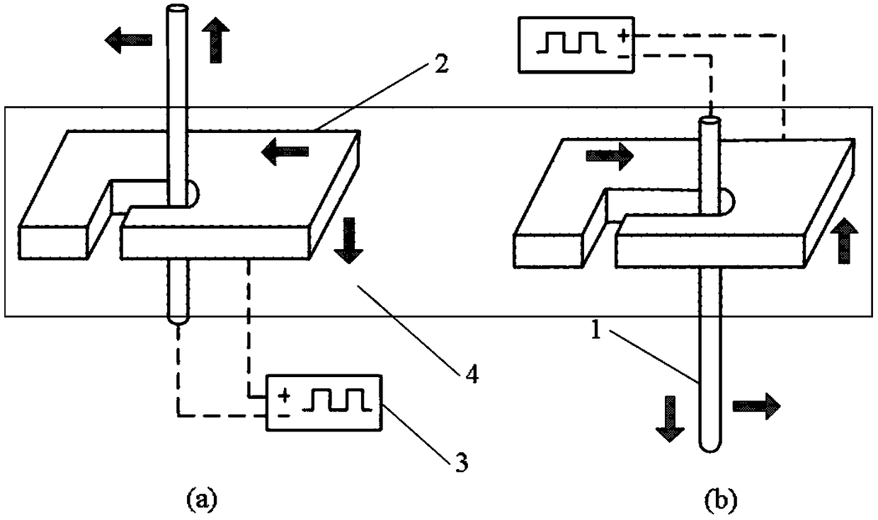
[0022] figure 1 In the schematic diagram of the fine electrolytic wire cutting machining method with different speed compound motion of the wire electrode workpiece, (a) is the different speed compound motion of the wire electrode relative to the workpiece, and (b) is the different speed compound motion of the workpiece relative to the wire electrode.

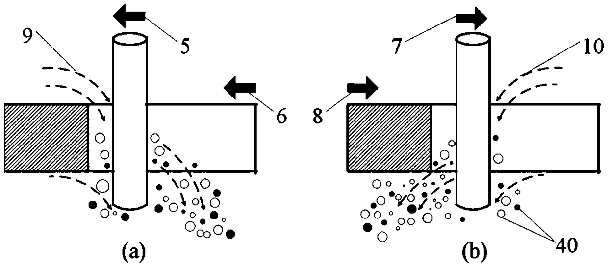
[0023] figure 2 In the X-Y feed cutting process and product discharge schematic diagram of the wire electrode workpiece shown, (a) is the different speed feed movement of the wire electrode relative to the workpiece, and (b) is the different speed feed movement of the workpiece relative to the wire electrode.

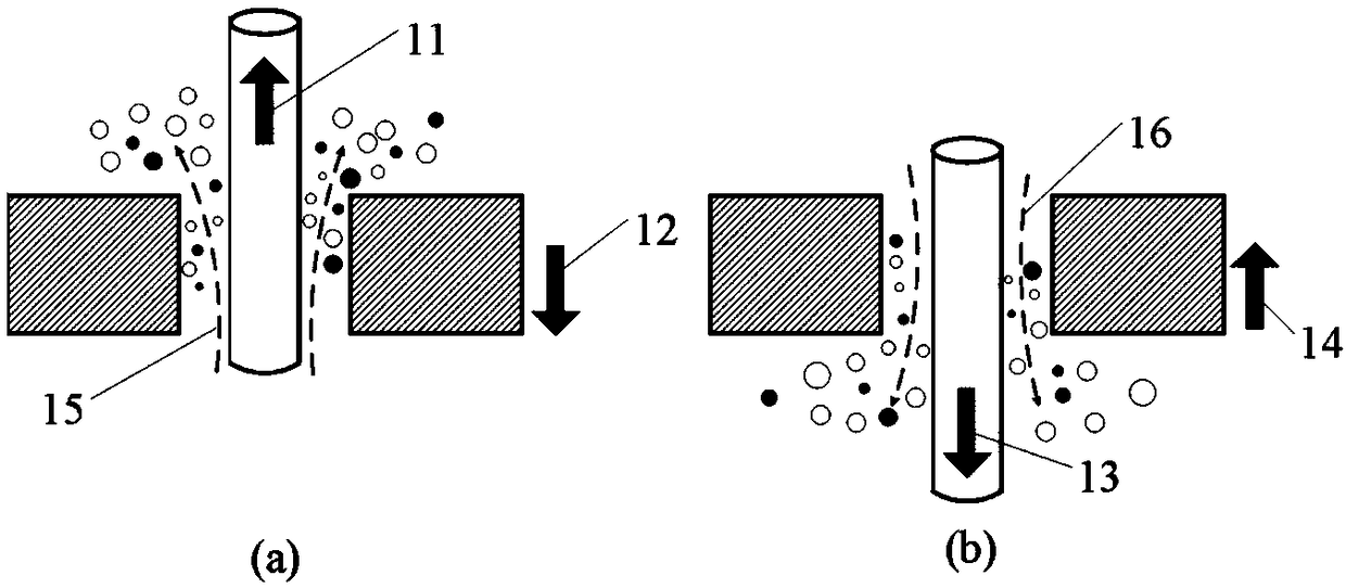
[0024] image 3 In the schematic diagram of Z-direction reciprocating motion and product discharge of the wire electrode workpiece shown, (a) is the relative motion of the wire electrode and the workpiece, and (b) is the opposite motion of the wire electrode workpiece.

[0025] Figure 4 The schematic diagram of the ...


PUM


Abstract

The invention relates to a line electrode workpiece different-speed compound motion micro electrolytic line cutting machining method, and belongs to the field of precision micro electrochemical manufacturing. In the machining direction, the line electrode and the workpiece perform relative cutting motion at different speeds, and stationary electrolyte flows reversely and rapidly to flush out products in a gap. In the direction perpendicular to the machining direction, the line electrode and the workpiece move alternately in a reciprocating mode to assist mass transfer in the gap. By using thecompound motion in different directions, the position change of a machining area is realized, the electrolyte in the machining gap is driven to rapidly renew and flow, and the differential motion micro-electrolysis line cutting machining is carried out under the state of high-efficiency mass transfer. The line electrode workpiece different-speed compound motion micro electrolytic line cutting machining method remarkably improves the precision, efficiency and stability of micro-electrolysis line cutting machining, and has important significance.

Description

technical field [0001] The invention relates to a fine electrolytic wire cutting processing method of a wire electrode workpiece with different speed compound motion, belonging to the field of precision fine electrochemical manufacturing. Background technique [0002] Precision and miniaturization are the mainstream development trends of modern industrial products. In micromechanical systems, metal microdevices have the characteristics of high strength, low resistivity, high sensitivity and high density. The demand is increasing day by day, and the materials and structural forms involved are also increasing. Different, the planar profile microstructure is an important structural form, which is widely used in many fields such as aerospace, biomedicine, precision instruments, micro-robots, and micro-sensors due to its excellent performance. [0003] Micro-electrolytic wire cutting technology uses micro-scale metal wires as tool electrodes. Based on the principle of electrochem...

Claims


Application Information

Patent Timeline
Patent Type & Authority Applications(China)
IPC IPC(8): B23H7/02B23H7/30B23H7/36B23H11/00
CPCB23H7/02B23H7/30B23H7/36B23H11/00
Inventor 毕晓磊曾永彬曲宁松杨涛
Owner NANJING UNIV OF AERONAUTICS & ASTRONAUTICS
Why Eureka
Try Eureka