Supercharge Your Innovation With Domain-Expert AI Agents!

Tire face tread pattern structure

A pattern structure and tire tread technology, applied in tire tread/tread pattern, tire parts, transportation and packaging, etc., can solve problems such as inability to cope with light off-road roads, to ensure off-road performance, improve skid resistance, Increase the effect of edge effects

Pending Publication Date: 2018-11-13
CHENG SHIN RUBBER (XIAMEN) IND LTD
View PDF0 Cites 2 Cited by
  • Summary
  • Abstract
  • Description
  • Claims
  • Application Information

AI Technical Summary

Problems solved by technology

[0008] Therefore, the above three methods have indeed improved the performance of ice and snow roads to a certain extent, but at the same time they also bring the above-mentioned negative effects, and cannot cope with the ice and snow and light off-road roads that fat cars pass through.

Method used


Image

  • Tire face tread pattern structure
  • Tire face tread pattern structure
  • Tire face tread pattern structure

Examples


Embodiment approach

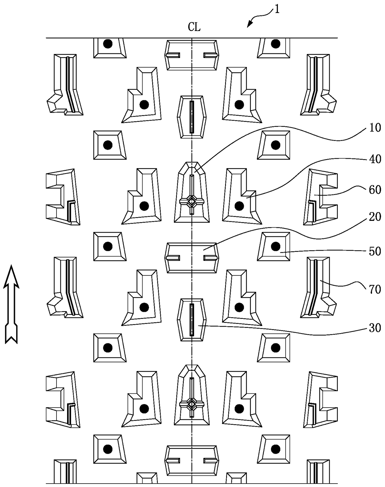
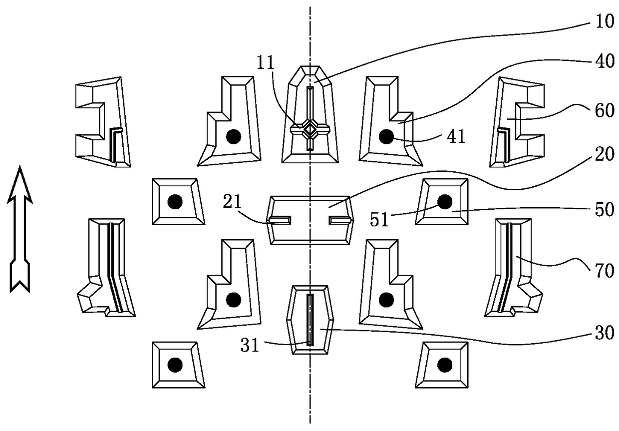
[0044] Such as Figure 1 to Figure 7 As shown, the present invention discloses a tire tread pattern structure, wherein: the vertical direction is set as the tire radial direction, the lateral direction is set as the tire axial direction, the single dotted line represents the equatorial plane, and the arrow points to the tire's running direction. The end of the pattern block pointing to the driving direction represents the front end, the end of the pattern block opposite the traveling direction represents the rear end, the end of the pattern block close to the tread centerline CL represents the inner end, and the end of the pattern block away from the tread centerline CL represents the outer end. In addition, the terms "first", "second", "third", etc. are only used to describe a feature, and should not be construed as indicating or implying the quantity of the feature.

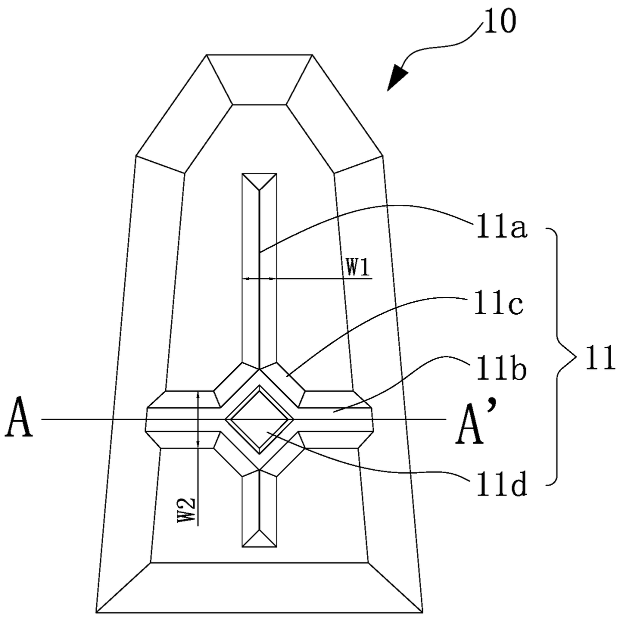
[0045] Such as figure 1 , 2 As shown, the tire tread 1 of the present invention is provided with a plural...


PUM


Abstract

The invention discloses a tire face tread pattern structure. A plurality of thread pattern block units are arranged in the circumferential direction of the periphery of the tire face at intervals. Thetread pattern block units comprise protruding tread pattern blocks arranged on the tire surface. The protruding tread pattern blocks are arranged to be a first center block, a second center block anda third center block with cross-shaped anti-skid portions arranged at a tire face center line of the block units, a first tire shoulder block and a second tire shoulder block which are arranged at the tire shoulder position, and two first transition blocks and two second transition blocks which are arranged at the transition area between the tire face center line and the tire shoulder. The treadpattern blocks are arranged to be polygons. The second center block and the third center block are arranged to be a whole transverse tread pattern block and a whole longitudinal tread pattern block with the left and right ends protruding outwards. The first transition block is in a b shape with the front end being narrow and the rear end being wide. The second transition block is in a quadrilateral shape. The performances of anti-skid, ground holding and traction of the tire are improved, rigidity of the tread pattern blocks is achieved, and off-road performance is guaranteed.

Description

technical field [0001] The present invention relates to a pneumatic tire, and more particularly to a tread pattern structure of a pneumatic tire for mountain bikes. Background technique [0002] The fat bike is a new model extended from mountain bikes. It mainly travels on ice and snow and light off-road roads. Compared with traditional mountain bikes, the road conditions used by this model are relatively flat, and its supporting tires have a larger broken width. Therefore, compared with traditional mountain bikes The carcass of the tire is wider, the shock absorption and cushioning effect are good, and the riding stability is good when used in wild road conditions. However, the road surface in winter is covered with ice and snow. Inadequate traction performance. [0003] Ignoring the impact of materials on tire performance, the following three methods are currently used to improve anti-skid, grip and traction performance: [0004] 1. Set serrated or wavy knife grooves on ...

Claims


Application Information

Patent Timeline
Patent Type & Authority Applications(China)
IPC IPC(8): B60C11/03
CPCB60C11/03B60C11/0327B60C2011/0358B60C2011/0353B60C2011/0365B60C2011/0341
Inventor 林文艳林冠宏
Owner CHENG SHIN RUBBER (XIAMEN) IND LTD
Features
  • R&D
  • Intellectual Property
  • Life Sciences
  • Materials
  • Tech Scout
  • Unparalleled Data Quality
  • Higher Quality Content
  • 60% Fewer Hallucinations
Learn More