Storable spinning machine convenient to use
A textile machine and textile technology, which is applied in textile, loom, textile and paper making, etc., can solve the problem of inconvenient movement of textile machines, and achieve the effect of easy movement, good safety and physical strength saving.
- Summary
- Abstract
- Description
- Claims
- Application Information
AI Technical Summary
Problems solved by technology
Method used
Image

Examples
specific Embodiment approach 1
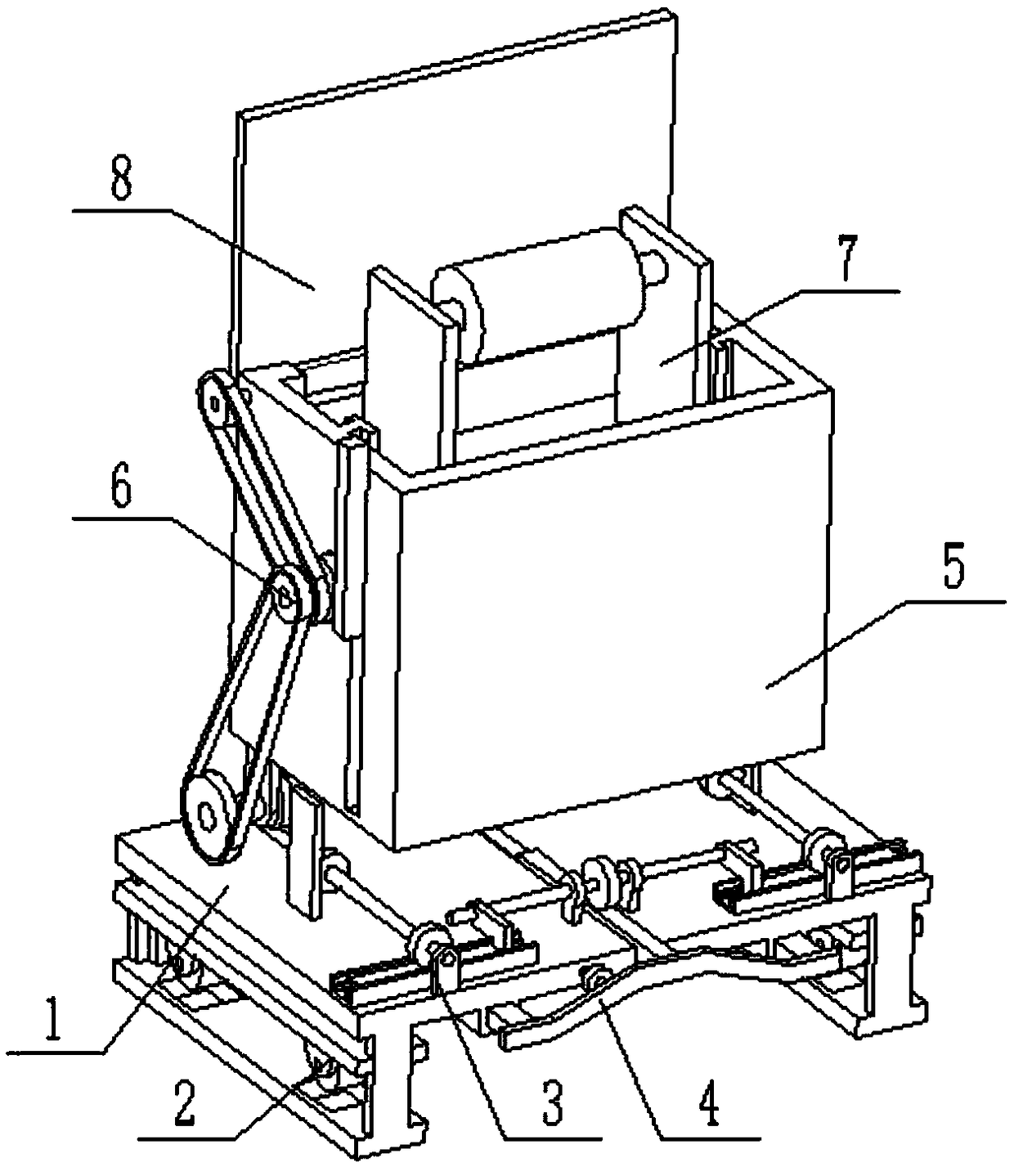
[0027] Combine below Figure 1-9Describe this embodiment, a kind of portable textile machine that can be easily moved, including a support base 1, a moving pulley assembly 2, a pulley drive assembly 3, a pulley control assembly 4, a textile machine storage seat 5, a linkage mechanism 6, a textile machine assembly 7 and The top cover 8, the moving pulley assembly 2 is provided with two, the two moving pulley assemblies 2 are symmetrically slidably connected to the two ends of the support base 1, the pulley drive assembly 3 is fixedly connected to the support base 1, and the pulley drive assembly 3 The two ends are connected to the two moving pulley assemblies 2 respectively, the pulley control assembly 4 is connected to the front end of the support base 1, the pulley control assembly 4 is connected to the pulley drive assembly 3 in transmission, and the textile machine storage seat 5 is fixedly connected to the support base 1. The lower end of the linkage mechanism 6 is connect...
specific Embodiment approach 2
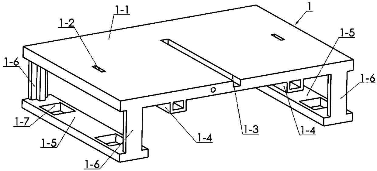
[0028] Combine below Figure 1-9 To illustrate this embodiment, the support base 1 includes a support base plate 1-1, a rack plate passing groove 1-2, a rack plate chute 1-3, a fixed sliding sleeve 1-4, and a foot support plate 1-5 , the T-shaped connecting plate 1-6 and the pulley pass through the groove 1-7, and the support base plate 1-1 is symmetrically provided with two rack plate chute 1-2, and the upper ends of the two foot support plates 1-5 are respectively fixedly connected There are two T-shaped connecting plates 1-6, and the two foot supporting plates 1-5 are fixedly connected to the left and right ends of the supporting base plate 1-1 through the T-shaped connecting plates 1-6, and the bottom supporting plates 1-5 The front and rear ends are provided with pulley passage grooves 1-7; the middle end of the support base plate 1-1 is provided with a rack plate chute 1-3, and the lower end of the support base plate 1-1 is symmetrically fixedly connected with two fixed ...
specific Embodiment approach 3
[0031] Combine below Figure 1-9 To illustrate this embodiment, the pulley drive assembly 3 includes a worm seat 3-1, a worm 3-2, a shaft seat 3-3, a shaft 3-4, a drive gear 3-5, a transmission gear 3-6, and a screw seat 3 -7, two-way screw rod 3-8, control gear 3-9, linkage block 3-10, I-shaped rack 3-11, slide seat 3-12 and I-shaped chute 3-13, worm screw 3-2 Both ends are rotatably connected to the two worm seats 3-1 through bearings with seats, and the two worm seats 3-1 are fixedly connected to the left end of the support base plate 1-1, and both ends of the rotating shaft 3-4 are rotated through bearings with seats Connected to the two rotating shaft seats 3-3, the two rotating shaft seats 3-3 are fixedly connected to the right end of the support base plate 1-1, and the middle ends of the worm screw 3-2 and the rotating shaft 3-4 are respectively fixedly connected to a driving gear 3-5 , the front ends of the worm 3-2 and the rotating shaft 3-4 are respectively fixedly ...
PUM
 Abstract
Description
Claims
Application Information
 - R&D
- Intellectual Property
- Life Sciences
- Materials
- Tech Scout
- Unparalleled Data Quality
- Higher Quality Content
- 60% Fewer Hallucinations
Browse by: Latest US Patents, China's latest patents, Technical Efficacy Thesaurus, Application Domain, Technology Topic, Popular Technical Reports.
© 2025 PatSnap. All rights reserved.Legal|Privacy policy|Modern Slavery Act Transparency Statement|Sitemap|About US| Contact US: help@patsnap.com