Haze pollutant removal system

A pollutant and smog technology, applied in the field of smog and haze, can solve the problems of large space occupation, easy friction damage, inconvenient movement, etc., to achieve the effect of convenient installation and disassembly, prevention of friction damage, and prevention of inconvenient movement

Inactive Publication Date: 2018-12-18
CHENGDU FUYANG TECH DEV
View PDF6 Cites 5 Cited by
  • Summary
  • Abstract
  • Description
  • Claims
  • Application Information

AI Technical Summary

Problems solved by technology

[0003] After searching, the Chinese patent discloses a wind-driven sprayer (authorized announcement number CN203816819U) for removing smog. This patented technology can make the range variable, the coverage area large, and the particles small. A kind of moist mist, which can quickly settle down the dust, with flexible supporting power, can be fixedly installed on the platform, and can also be installed on various transportation platforms. It can be installed on the vehicle and can be sprayed while driving. It is flexible in operation and high in safety. , but the installation of the fixed seat and the water storage tank of the existing air-driven sprayer is divided into two types, one is separated, and the other is integrated. The separated sprayer is caused by the length limitation of the water pipe when it is working. It is unstable when working, and the integrated sprayer takes up a lot of space when it is in use, which makes it inconvenient to move, and the water storage tank is easily damaged by friction with the inner wall of the fixed shell when it is placed, and the water storage tank collides with the inner wall of the fixed shell during the movement The resulting shell of the water storage tank is easily deformed and damaged, and the water inside the water storage tank cannot be filtered during the pumping process, which may easily cause impurities to block the spray head and affect the spray effect, and it is not more convenient for the user to adjust the spray angle of the spray barrel

Method used


Image

  • Haze pollutant removal system
  • Haze pollutant removal system
  • Haze pollutant removal system

Examples


Embodiment Construction

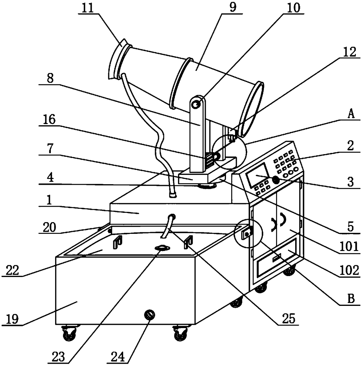
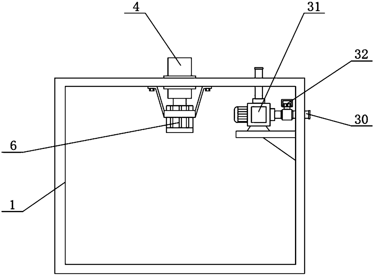
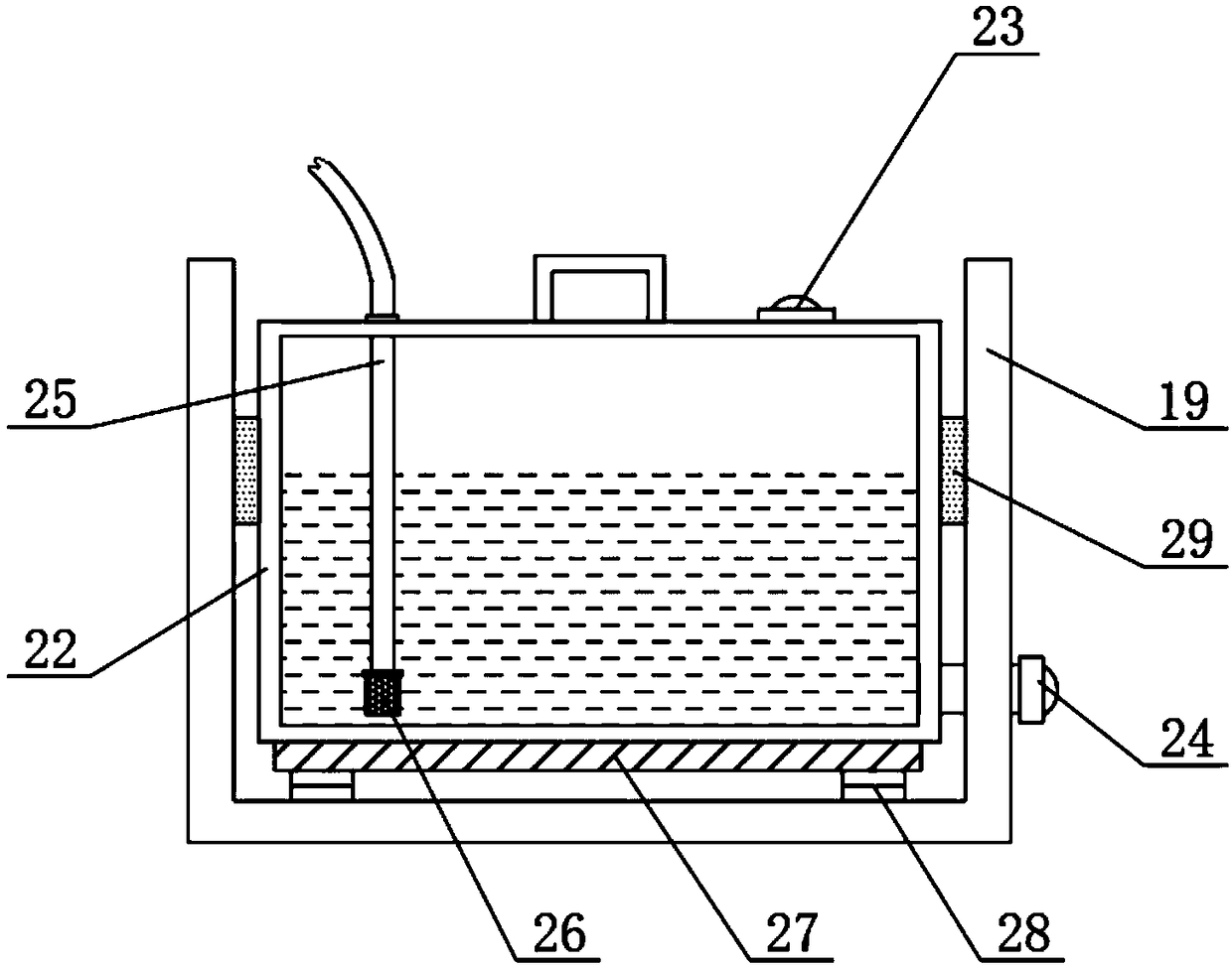
[0028] see Figure 1 to Figure 7, in an embodiment of the present invention, a haze pollutant removal system includes a fixed base 1, an operating console 2 is arranged on the top of the fixed base 1, a display screen 3 is arranged on the operating console 2, and a The center is provided with a rotating shaft 4, the top of the rotating shaft 4 is connected to the turntable 5, the bottom of the rotating shaft 4 is connected to the inside of the fixed seat 1, and the first servo motor 6 is connected, and the top of the turntable 5 is connected to a support plate 7, Above the support plate 7 is provided with a spray barrel 9, and the top of the support plate 7 is located at both sides of the spray barrel 9 and is connected with a support rod 8, and the top of the support rod 8 is connected with a Fixed shaft 10, the top of spray gun barrel 9 is provided with protective cover 11, and spray nozzle 13 is installed at the inboard edge place of protective cover 11, and the inside of s...


PUM


Abstract

The invention discloses a haze pollutant removal system. The system comprises a fixed seat, an operating table is arranged at the top of the fixed seat, a display screen is arranged on the upper surface of the operating table, a rotating shaft is arranged at the center of the top of the fixed seat, the top end of the rotating shaft is connected with a rotating disc, the bottom end, located in thefixed seat, of the rotating shaft is connected with a first servo motor, the top end of the rotating disc is connected with a supporting plate, a spray gun barrel is arranged above the supporting plate, and the top end, located at two sides of the spray gun barrel, of the supporting plate are connected with supporting rods. The system is convenient for preventing a water storage tank from being damaged by friction with the inner wall of a fixed shell when the system stands and preventing the deformation damages of the shell of the water storage tank, caused by the collision between the water storage tank and the inner wall of the fixed shell in the movement process of the system, can filter water in the water storage tank in the extraction process to prevent the influences of blocking of aspray head by impurities on the spraying effect, and makes the spray angle of the spray gun barrel easily adjusted.

Description

technical field [0001] The invention relates to the technical field of haze removal, in particular to a haze pollutant removal system. Background technique [0002] Haze is a combination of fog and haze. Haze is common in cities. In many areas of China, fog is incorporated into haze as a disastrous weather phenomenon for early warning and forecasting. It is collectively referred to as "smog weather". Haze is a specific climatic condition. As a result of interaction with human activities, the economic and social activities of high-density population will inevitably emit a large amount of fine particulate matter (PM2.5). Once the emission exceeds the atmospheric circulation capacity and carrying capacity, the concentration of fine particulate matter will continue to accumulate. Due to the influence of stable weather, large-scale smog is very easy to appear. The existence of smog has greatly affected people's living environment and health. Therefore, it is urgent to deal with s...

Claims


Application Information

Patent Timeline
Patent Type & Authority Applications(China)
IPC IPC(8): B01D47/06
CPCB01D47/06B01D2221/08B01D2221/16B01D2247/08
Inventor 车国容
Owner CHENGDU FUYANG TECH DEV
Why Eureka
Try Eureka