Novel gear and gear rack drive mechanism used for rope twisting knotting machine

A technology of rack and pinion and transmission mechanism, which is applied in knotting, textile and papermaking, etc., can solve the problems of high production cost, affecting the knotting effect, unable to achieve the knot spacing, etc., and achieves the effect of simple structure and convenient assembly.

Pending Publication Date: 2018-11-13
WUXI XIANGHONG IND & TRADE CO LTD
View PDF1 Cites 2 Cited by
  • Summary
  • Abstract
  • Description
  • Claims
  • Application Information

AI Technical Summary

Problems solved by technology

Disadvantages: one is that the knotting head in this kind of scarf twisting rope knotting machine is not only complicated in structure, but the production cost is high; the other is that there is only one hook in the knotting head, s

Method used


Image

  • Novel gear and gear rack drive mechanism used for rope twisting knotting machine
  • Novel gear and gear rack drive mechanism used for rope twisting knotting machine

Examples


Embodiment Construction

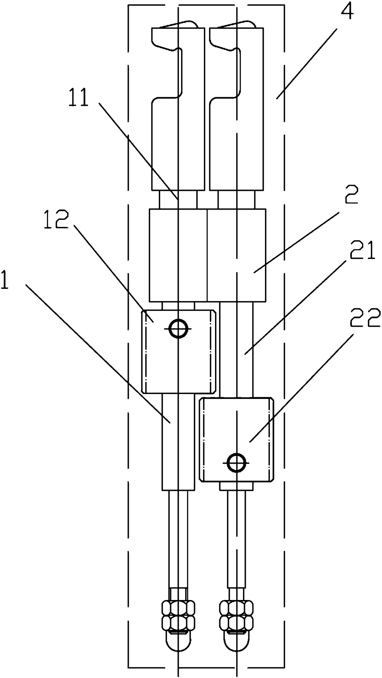
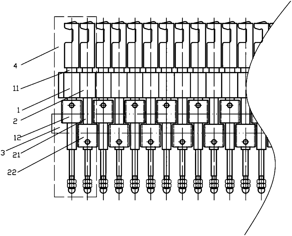
[0011] As shown in the figure, a new type of rack and pinion transmission mechanism for a rope knotting machine includes a knotting claw one 1, a knotting claw two 2 and a rack 3, and the knotting claw one 1 includes a claw rod one 11 and gear one 12, said gear one 12 is located on the claw lever one 11, said knotting claw two 2 comprises claw lever two 21 and gear two 22, and said gear two 22 is also located on the claw lever two 21, The level of the first gear 12 is higher than that of the second gear 22, and part of the second gear 22 is accommodated in the gap between the first gear 12 and the claw rod one 11. The first knotting claw 1 and the second knotting claw 2 constitute a knotting unit 4, the number of the knotting units 4 is several, and the rack 3 meshes with the gear one 12 and the gear two 22 in each knotting unit 4; the width d1 of the gear one 12 and the width d1 of the gear two The width d2 of 22 is the same; the width d3 of the rack 3 is the same as the widt...


PUM


Abstract

The invention relates to the field of application of rope twisting knotting machines, in particular to a novel gear and gear rack drive mechanism used for a rope twisting knotting machine. The novel gear and gear rack drive mechanism makes knotting spacing smaller, and is simpler in structure, more convenient to assemble and more stable in mechanical drive. The novel gear and gear rack drive mechanism comprises first knotting claws, second knotting claws and gear racks, the first knotting claws comprise first claw rods and first gears, the first gears are arranged on the first claw rods, the second knotting claws comprise second claw rods and second gears, and the second gears are also arranged on the second claw rods. The novel gear and gear rack drive mechanism is characterized in that the horizontal height of the first gears is larger than that of the second gears, part of the second gears are contained in the gaps between the first gears and the first claw rods, the first knottingclaws and the second knotting claws form multiple knotting units, and the gear racks are meshed with the first gears and the second gears in all the knotting units.

Description

technical field [0001] The invention relates to the application field of a rope knotting machine, in particular to a novel rack and pinion transmission mechanism for a rope knotting machine. Background technique [0002] CN102524992A, name "a scarf rubbing rope knotting machine", it includes a frame, a positioning device, a rope rubbing device and a knotting machine, the frame includes a bottom beam and a middle beam, and a hook knife runs through the middle of the bottom beam Groove, the lifting arrangement type hook knife is set in the hook knife groove in the middle of the bottom beam, the lower washboard is set on the bottom beam of the frame, the slideways are set on the left and right sides of the bottom beam, and the knotting machine is installed on the middle beam of the frame superior. The positioning device includes upper and lower pressing plates and slideways. The lower pressing plate is arranged on the slideways on both sides of the bottom beam and is parallel ...

Claims


Application Information

Patent Timeline
IPC IPC(8): D04G5/00
CPCD04G5/00
Inventor 张虹
Owner WUXI XIANGHONG IND & TRADE CO LTD
Why Eureka
Try Eureka