Cutting device

A cutting device and piston rod technology, applied in leather punching/punching/cutting, small raw hide/large raw hide/leather/fur treatment, animal husbandry, etc., can solve the problem of leather affecting cutting effect and save manpower The effect of high labor, cutting efficiency and simple operation

Active Publication Date: 2018-07-27
宁波隆锐机械制造有限公司
View PDF7 Cites 2 Cited by
  • Summary
  • Abstract
  • Description
  • Claims
  • Application Information

AI Technical Summary

Problems solved by technology

[0006] The purpose of the present invention is to provide a cutting device to solve the problem that the leathe

Method used


Image

  • Cutting device
  • Cutting device
  • Cutting device

Examples


Embodiment 1

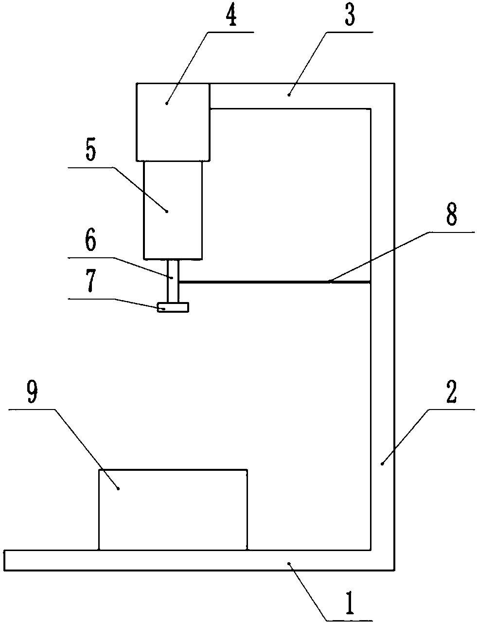
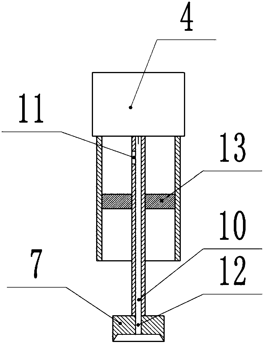
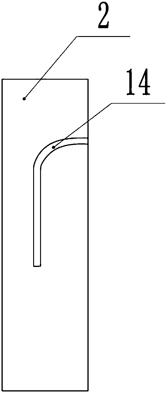
[0025] Such as figure 1 As shown, a cutting device includes a base 1, the left end of the base 1 is connected with a vertical pillar 2 through bolts, the upper end of the pillar 2 is welded with a horizontal beam 3, a lifting lug is installed on the beam 3, and a cylinder 4 is installed on the lifting lug , The cylinder 4 can swing back and forth; such as figure 2 As shown, the direction of the piston rod 6 of the cylinder 4 is vertically downward, and the inside of the piston rod 6 is provided with a vertical suction pipe 10; the lower end of the piston rod 6 is installed with an annular cutter head 7 through bolts, and the lower end of the annular cutter head 7 Facing inwardly, a suction hole 12 is opened on the axis of the annular cutter head 7, and the suction hole 12 is connected with the suction pipe 10; the upper end of the piston rod 6 is provided with an outlet hole 11, the diameter of the suction hole 12 is smaller than the outlet hole The aperture of 11. A sleeve 5 ...

Embodiment 2

[0028] Such as Figure 4 As shown, on the basis of the first embodiment, a rotary joint is connected between the annular cutter head 7 and the piston rod 6, an annular groove is opened on the outer side of the annular cutter head 7, and the output shaft is installed downward on the cross bar 8 through bolts. Connect the belt 16 between the output shaft of the motor 15 and the ring cutter head 7, and install the belt 16 in the ring groove. When the ring cutter head 7 does not sufficiently cut the leather, start the motor 15, motor 15 The belt 16 drives the ring cutter head 7 to rotate to fully cut the leather; a torsion spring is installed between the upper end of the cylinder 4 and the beam 3 to keep the cylinder 4 in a vertical state. When the cylinder 4 is tilted, When the spring and the piston rod 6 extend, the cylinder 4 can quickly assume a vertical state, which improves the cutting efficiency.


PUM


Abstract

The invention belongs to the technical field of cutting equipment and particularly discloses a cutting device. The cutting device comprises a base. The base is provided with a support column and a cross beam, wherein the support column and the cross beam are connected in sequence. The cross beam is provided with an air cylinder. A piston rod is provided with an annular cutter. The base is providedwith a workbench. The support column is provided with a sliding rail, the upper portion of the sliding rail is inclined towards one side. The piston rod is provided with an empty cavity structure, and the annular cutter is provided with an air sucking hole. A sleeve is arranged between the annular cutter and the air cylinder. The sleeve and the air cylinder are connected in a sealed manner. The middle of the piston rod is provided with a push plate fixedly connected with the piston rod, the upper portion of the piston rod is provided with an air discharging hole communicating with the empty cavity structure. A cross rod is connected between the piston rod and the sliding rail, the cross rod and the sliding rail are connected in a sliding manner. The air cylinder is inclined when the crossrod is located on the upper portion of the sliding rail. The cutting device is mainly used for cutting annular leather, and the problem that the cutting effect is poor in the leather cutting processis solved.

Description

Technical field [0001] The invention belongs to the technical field of cutting equipment, and specifically discloses a cutting device. Background technique [0002] Leather has good airtightness, and is widely used in clothing manufacturing, leather shoe manufacturing and decoration manufacturing. Leather clothes and wearables have better warmth retention. In winter, leather earmuffs can prevent people’s ears. Frostbite can prevent freezing and keep warm. [0003] When processing the earmuffs, it is usually necessary to cut the leather material into a circle and wrap it outside the thermal insulation material. The traditional leather cutting requires manual operation and the cutting efficiency is low. [0004] In view of the above problems, Chinese Patent CN105269607B discloses a circular cutting device for the outer skin of earmuffs, which includes a conveying support frame. The ground on both sides of the conveying support frame is fixed with support columns and upper support plat...

Claims


Application Information

Patent Timeline
IPC IPC(8): C14B5/00C14B17/00
CPCC14B5/00C14B17/00
Inventor 李龙德
Owner 宁波隆锐机械制造有限公司
Why Eureka
Try Eureka