Substrate for mirrors for EUV lithography

a mirror and lithography technology, applied in the field of substrates for euv lithography mirrors, can solve the problem of no longer being able to employ lens-like elements in transmission, and achieve the effect of avoiding adverse influences on the increasing the reflectivity of mirrors, and avoiding adverse effects on optical properties of optical elements

Active Publication Date: 2013-07-04
CARL ZEISS SMT GMBH
View PDF2 Cites 20 Cited by
  • Summary
  • Abstract
  • Description
  • Claims
  • Application Information

AI Technical Summary

Benefits of technology

[0006]The root-mean-square roughness, also called RMS roughness, is calculated from the mean of the squares of the deviation of the measurement points over the surface with respect to an average area which is placed through the surface such that the sum of the deviations relative to the average area is minimal. In particular for optical elements for EUV lithography, the roughness in a spatial frequency range of 0.1 μm to 200 μm is of particular importance in order to avoid adverse influences on the optical properties of the optical elements.
[0007]In particular in the EUV wavelength range, the proportion of stray light in the optical systems, such as, for instance, illumination system and in particular projection system, of projection exposure apparatuses for lithographic methods has a significant influence on the performance of the respective projection exposure apparatus. The proportion of stray light can be influenced by the roughness of the optical elements. By providing a substrate for further processing to form a mirror, which substrate comprises a main body and a polishing layer having a maximum thickness of approximately 10 μm with a root-mean-square roughness of a maximum of approximately 0.5 nm, preferably 0.3 nm, particularly preferably 0.2 nm, it is possible for the resulting mirror also to be used in EUV lithography. This is because, due to these features of the substrate, the proportion of stray light which arises at the mirror can be kept within a scope that does not have a disturbing effect on the lithographic process, and the reflectivity of the mirror can thus also be increased. In this case, the proposed substrate is suitable, in particular, for EUV mirrors which comprise a highly reflective coating which are based on a multilayer system composed of alternate layers of material having different real parts of the complex refractive index, through which a crystal having lattice planes at which Bragg diffraction takes place for use with normal incidence is in a way simulated. Alternatively, it is also possible to provide only one or a few metallic layers for use with grazing incidence of the EUV radiation. Highly reflective coatings is the term used at wavelengths in the EUV range if reflectivities of 60% or more are achieved. The reflectivity that can actually be achieved can be additionally increased with the aid of the substrate proposed here.
[0008]The proposed substrate has the advantage that, firstly, for the main body it is possible to choose a material that is suitable for use as an EUV mirror for example with regard to its strength. Secondly, the surface of the substrate can be optimized by the choice of a further material that can be polished well. The polishing layer substantially only influences the properties of the substrate surface, while the mechanical properties are determined by the main body.
[0009]Aluminum alloys have the advantage that they have high strengths at low density, in particular under even relatively high thermal load such as can occur in projection exposure apparatuses for EUV lithography. Also, they are readily commercially available, such that substrates comprising a main body composed of an aluminum alloy can also be economically expedient. In preferred embodiments, the main body is produced from an aluminum alloy having a higher strength and / or a higher hardness than aluminum. Such aluminum alloys, in particular, have the advantage of a long lifetime and high corrosion resistance, in particular in comparison with aluminum as main body material.

Problems solved by technology

If light in the extreme ultraviolet (EUV) wavelength range is employed, for instance at wavelengths of between approximately 5 nm and 20 nm, it is no longer possible to employ lens-like elements in transmission, rather illumination and projection lenses are constructed from mirror elements having highly reflective coatings adapted to the respective operating wavelength.

Method used


Image

  • Substrate for mirrors for EUV lithography
  • Substrate for mirrors for EUV lithography
  • Substrate for mirrors for EUV lithography

Examples


Embodiment Construction

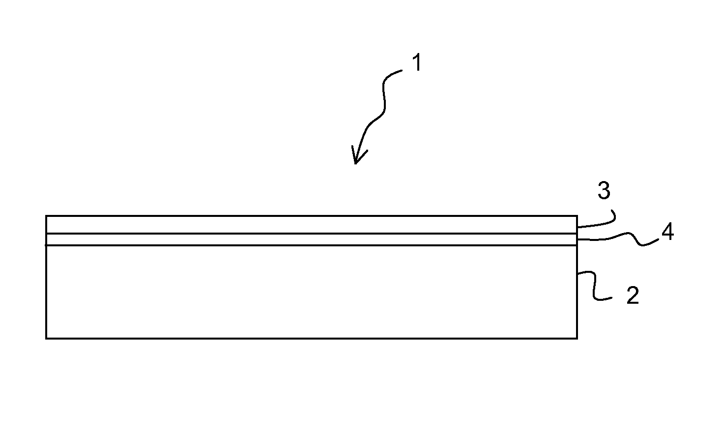
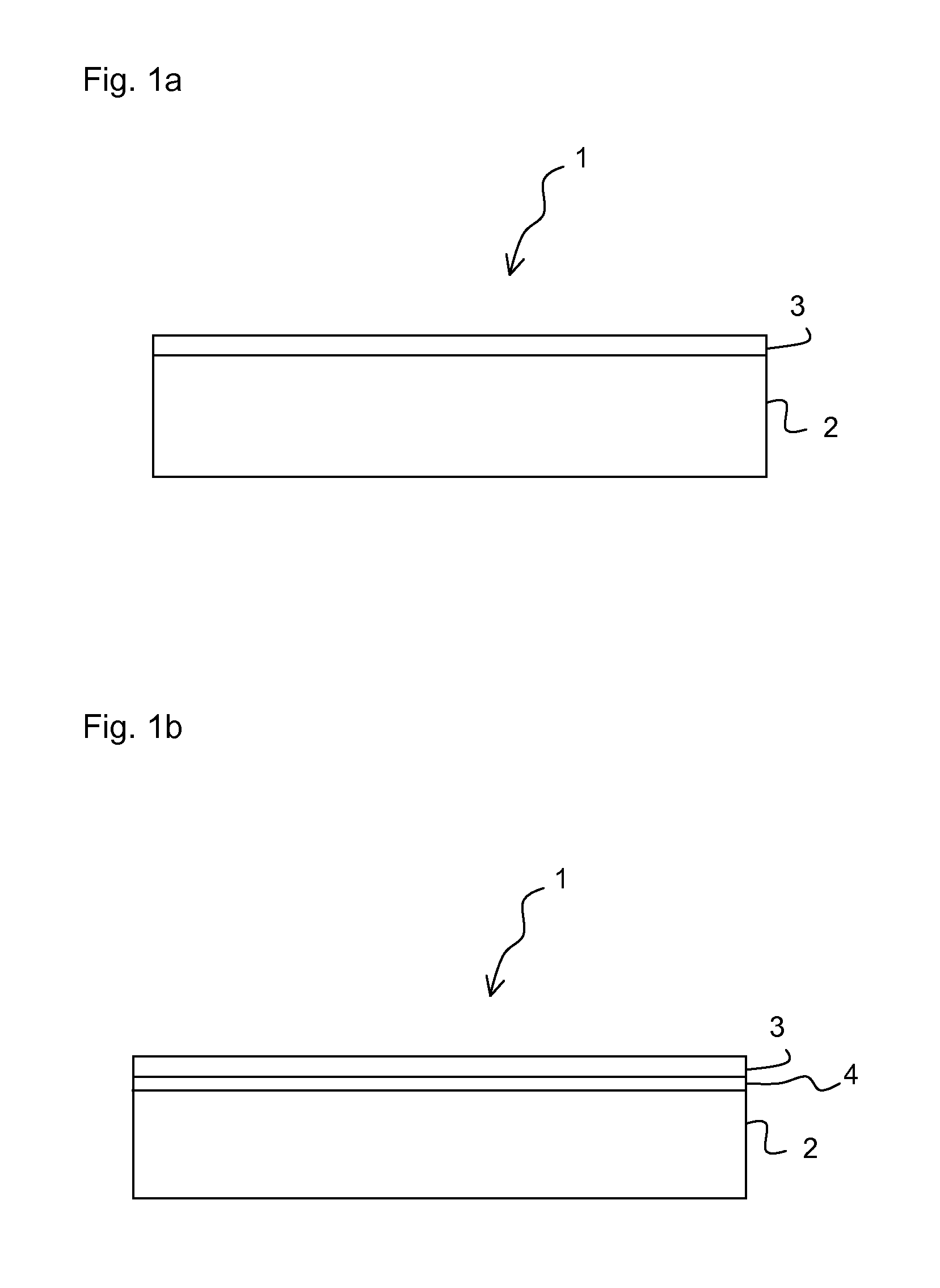
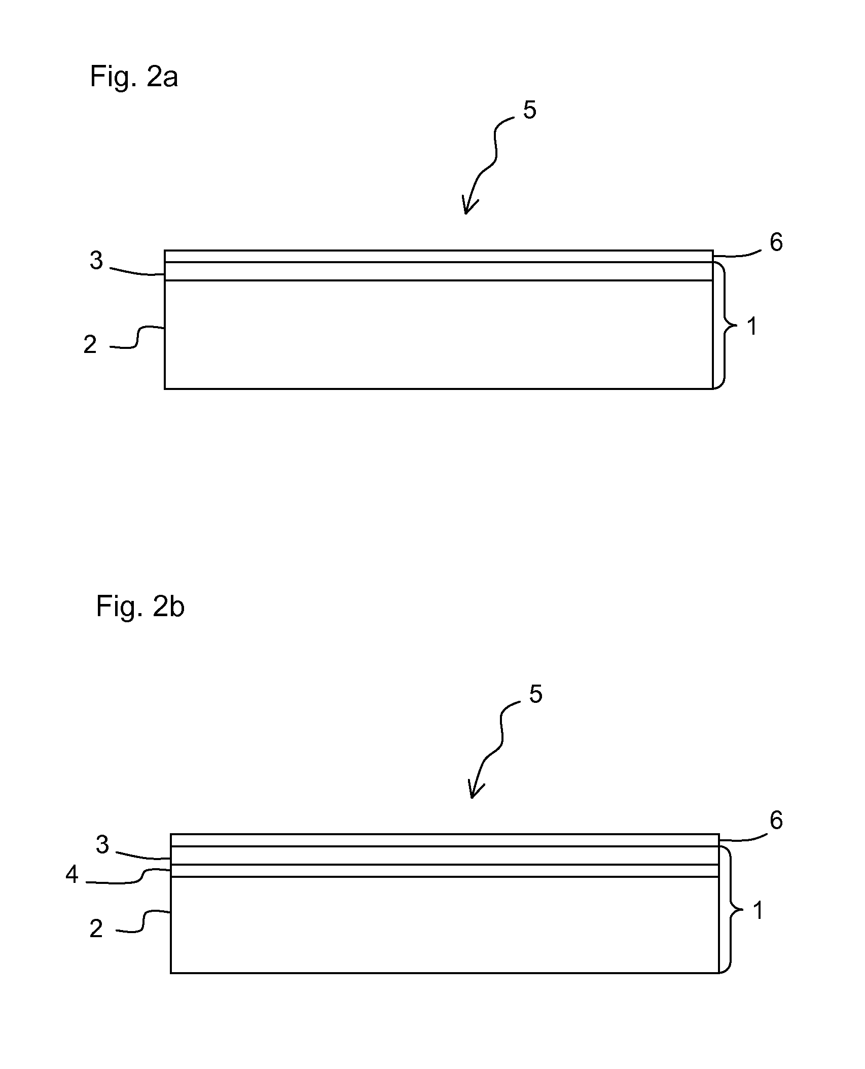
[0020]FIG. 1a schematically illustrates a first variant of an embodiment of a substrate 1 comprising a main body 2 and a polishing layer 3 applied thereto. The main body 2 and the polishing layer 3 perform different functions. While a good dimensional stability is of primary significance for the main body 2, good processability and polishability are primarily of importance in the case of the polishing layer 3.

[0021]The polishing layer can be applied using customary vacuum coating methods such as, for example, sputtering methods, electron beam evaporation, molecular beam epitaxy or ion beam assisted coating. If the polishing layer is a metallic material, for example copper, nickel-phosphorus or nickel-boron, it is preferably applied in an externally electroless way. In particular nickel-phosphorus or nickel-boron polishing layers can also be applied as dispersion layers, wherein polytetrafluoroethylene, for example, can serve as dispersant.

[0022]In particular nickel-phosphorus or nic...


PUM

PropertyMeasurementUnit
root-mean-square roughnessaaaaaaaaaa

Abstract

Substrates suitable for mirrors which are used at wavelengths in the EUV wavelength range have a main body (2) and a polishing layer (3). The polishing layer (3) has a thickness of less than 10 μm and a root-mean-square roughness of less than 0.5 nm and the main body (2) is produced from an aluminum alloy. Moreover, a highly reflective layer (6) is provided on the polishing layer (3) of the substrate (1) of the EUV mirror (5).

Description

[0001]This application is a Continuation of International Application No. PCT / EP2011 / 064904, with an international filing date of Aug. 30, 2011, which was published under PCT Article 21(2) in German, and which claims priority to German patent Application No. 10 2010 039 927.2 filed on Aug. 30, 2010. The entire disclosures of these parent patent applications are incorporated into the present Continuation by reference.FIELD OF AND BACKGROUND OF THE INVENTION[0002]The present invention relates to a substrate for a mirror for EUV lithography comprising a main body and a polishing layer, and to a mirror for an EUV projection exposure apparatus, comprising such a substrate and a highly reflective layer on the polishing layer.[0003]In order to be able to produce ever finer structures during the production of, for example, semiconductor components by lithographic methods, light having ever shorter wavelengths is employed. If light in the extreme ultraviolet (EUV) wavelength range is employe...

Claims


Application Information

Patent Timeline
Patent Type & Authority Applications(United States)
IPC IPC(8): G02B5/08
CPCG02B5/0808G03F7/70891G02B5/0891G21K1/06G03F7/70958
Inventor EKSTEIN, CLAUDIALIPPERT, JOHANNESMALTOR, HOLGERWEISER, MARTINSIEKMANN, HEIKODINGER, UDO
Owner CARL ZEISS SMT GMBH
Why Eureka
Try Eureka