Hydraulic motor cylinder block oil distribution disc assembly and machining method thereof

A processing method and technology of hydraulic motor, applied in servo motor components, fluid pressure actuating devices, mechanical equipment, etc., can solve the problems of small equipment clearance, damaged assembly parts, large assembly clearance, etc., to ensure the transmission performance and prolong the use. The effect of high life and high machining accuracy

Inactive Publication Date: 2018-04-24
SICHUAN QIXING ELECTRONICS
View PDF0 Cites 2 Cited by
  • Summary
  • Abstract
  • Description
  • Claims
  • Application Information

AI Technical Summary

Problems solved by technology

At present, the oil distribution mechanism mainly adopts the planar flow distribution type, that is, the oil distribution plate is installed on the end surface of the cylinder body along the axial direction, and closely cooperates with the end surface of the cylinder body to complete the oil inlet and outlet, and then convert the hydraulic energy into mechanical energy; this assembly Defects in the method: each part is prepared separately and directly assembled, and the spherical surface is not matched one by one to remove the processed burrs. The consequence is that the assembly gap is too large, and the noise generated during operation is large, which not only causes environmental pollution , and also affects the transmission performance between various components; if the equipment gap is too small, it will directly cause damage to the internal components of the hydraulic motor and cause failure; at the same time, there is no assembly guide during the assembly process, which may easily cause damage to the assembly parts

Method used


Image

  • Hydraulic motor cylinder block oil distribution disc assembly and machining method thereof
  • Hydraulic motor cylinder block oil distribution disc assembly and machining method thereof
  • Hydraulic motor cylinder block oil distribution disc assembly and machining method thereof

Examples


Embodiment Construction

[0042] All the features disclosed in this specification, except mutually exclusive features and / or steps, can be combined in any way.

[0043] The present invention will be described in detail below in conjunction with the accompanying drawings.

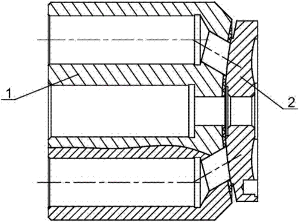
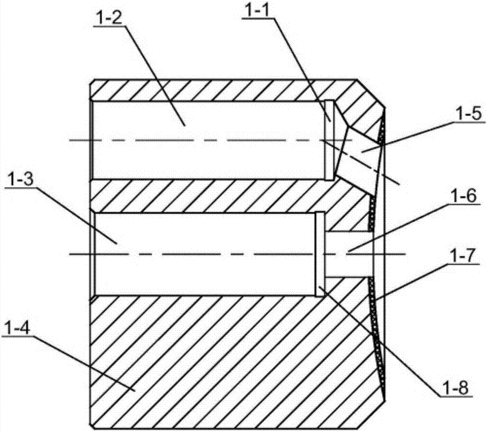
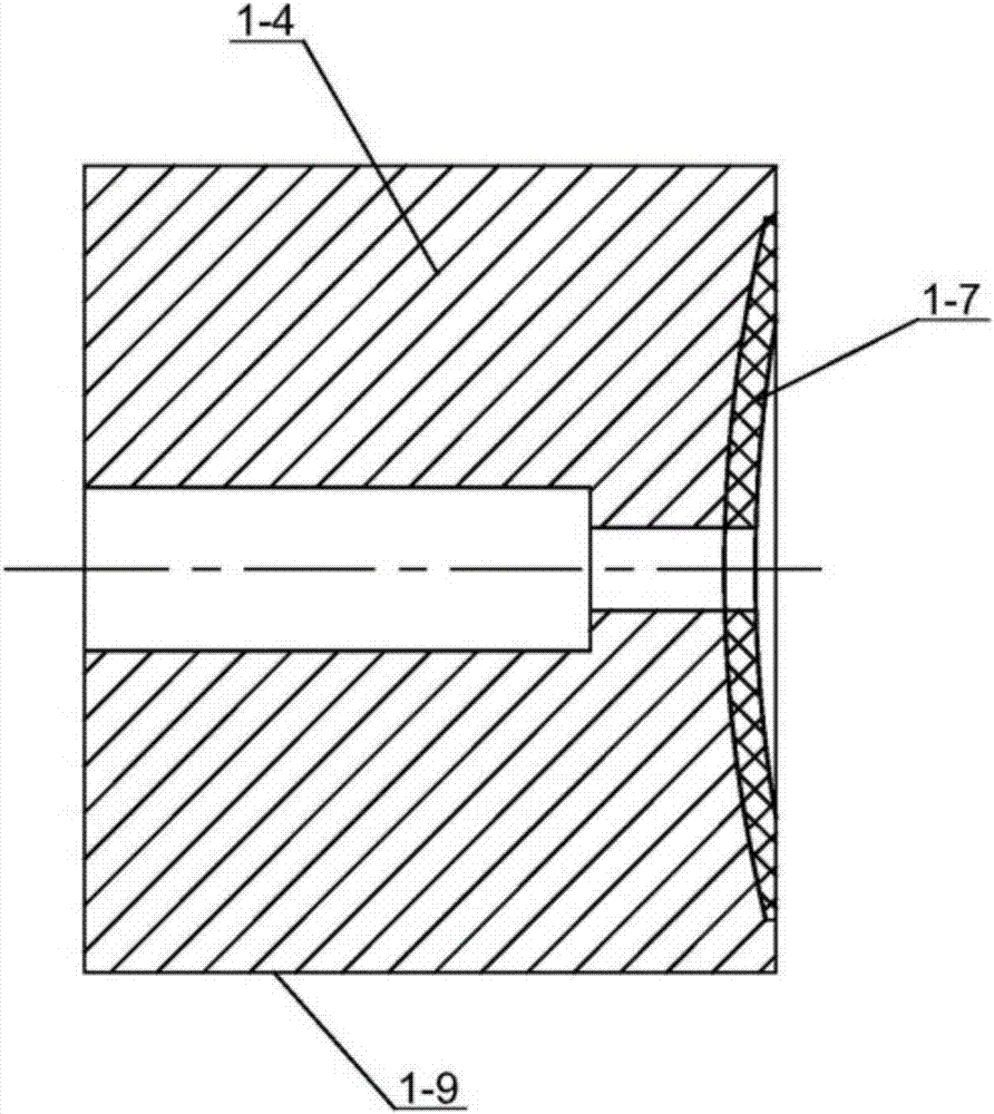
[0044] see Figure 1 to Figure 9 A hydraulic motor cylinder oil distribution plate assembly, including a plunger cylinder 1, a plunger chamber process groove 1-1, a plunger chamber 1-2, a connecting rod chamber 1-3, and a cylinder body 1- 4. Cylinder body oil circuit 1-5, cylinder body flushing oil circuit 1-6, sintered copper 1-7, connecting rod cavity process tank 1-8, cylinder outer circle 1-9, oil distribution plate 2, vibration reduction Groove, oil discharge channel 2-2, oil distribution plate flushing oil circuit 2-3, oil distribution plate processing sink groove 2-4, oil distribution plate positioning pin hole 2-5, oil distribution plate installation positioning sink groove 2-6 , The left process cone surface 2-7 of the oil...


PUM

PropertyMeasurementUnit
sizeaaaaaaaaaa
Cylindricityaaaaaaaaaa
surface roughnessaaaaaaaaaa

Abstract

The invention relates to the technical field of hydraulic system executive components, and discloses a hydraulic motor cylinder oil distribution plate assembly and a processing method thereof, including a plunger cylinder and an oil distribution plate. The plunger cylinder includes a cylinder body and sintered copper. Sintered copper is sintered on the main body of the cylinder body. A connecting rod cavity is set in the center of the plunger cylinder body, and a plunger cavity is set on the periphery of the connecting rod cavity. The oil channel is connected, and the oil discharge channel is provided with a vibration-reducing groove; the oil distribution plate is provided with a positioning pin hole of the oil distribution plate and the flushing oil circuit of the oil distribution plate; Oil pan right craft cone. The invention has the characteristics of wear resistance, corrosion resistance and impact resistance, and has high processing precision; it not only reduces the noise generated when the hydraulic motor is running, but also can ensure the transmission performance of each component, and is equipped with assembly guides to avoid damage to assembly parts and effectively prolong the life of the hydraulic motor. Component life.

Description

technical field [0001] The invention relates to the technical field of hydraulic system actuators, in particular to a hydraulic motor cylinder oil distribution plate assembly and a processing method thereof. Background technique [0002] In the axial piston hydraulic motor, the oil distribution mechanism is one of the key components of the hydraulic motor. Whether its structure, size and machining accuracy are reasonable or not directly affects the working reliability, volumetric efficiency and service life of the hydraulic motor. At present, the oil distribution mechanism mainly adopts the planar flow distribution type, that is, the oil distribution plate is installed on the end face of the cylinder body along the axial direction, and is closely matched with the end face of the cylinder body to complete the oil inlet and discharge, and then convert the hydraulic energy into mechanical energy; this assembly Defects in the method: each part is prepared separately and directly...

Claims


Application Information

Patent Timeline
Patent Type & Authority Applications(China)
IPC IPC(8): B23P15/00F15B13/04F15B15/14
CPCB23P15/00F15B13/04F15B15/1428
Inventor 江明泓
Owner SICHUAN QIXING ELECTRONICS
Why Eureka
Try Eureka