Pump body assembly, fluid machine and heat-exchange equipment

A component and pump body technology, applied in mechanical equipment, pump components, liquid fuel engines, etc., can solve the problems of easy eccentric rotation of the piston sleeve, affecting the working efficiency of the pump body assembly, etc.

Pending Publication Date: 2018-11-13
GREE ELECTRIC APPLIANCES INC
View PDF5 Cites 3 Cited by
  • Summary
  • Abstract
  • Description
  • Claims
  • Application Information

AI Technical Summary

Problems solved by technology

[0003] The main purpose of the present invention is to provide a pump body assembly, fluid machinery and heat exchange equipment to solve the problem in the prior art that the piston sleeve of the pump body assembly is prone to eccentric rotation and affects the working efficiency of the pump body assembly

Method used


Image

  • Pump body assembly, fluid machine and heat-exchange equipment
  • Pump body assembly, fluid machine and heat-exchange equipment
  • Pump body assembly, fluid machine and heat-exchange equipment

Examples


Embodiment 1

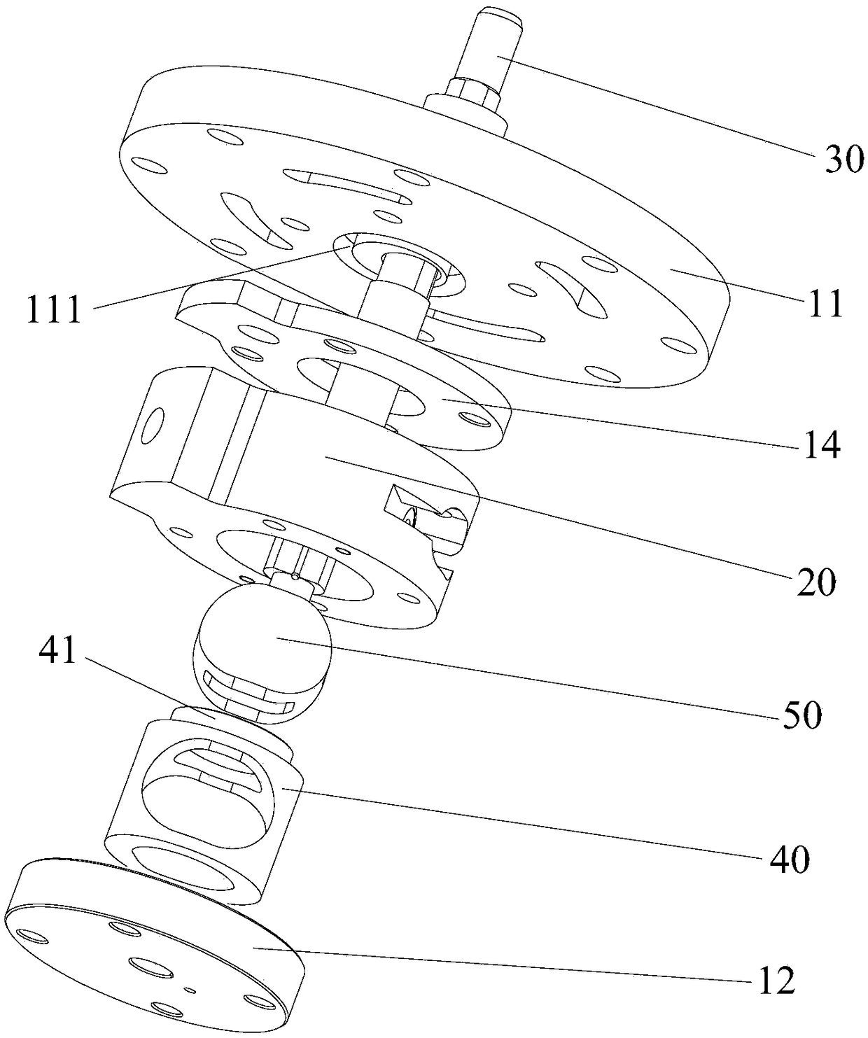
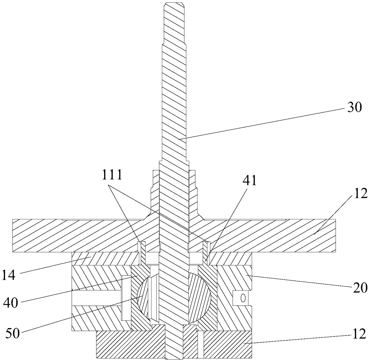
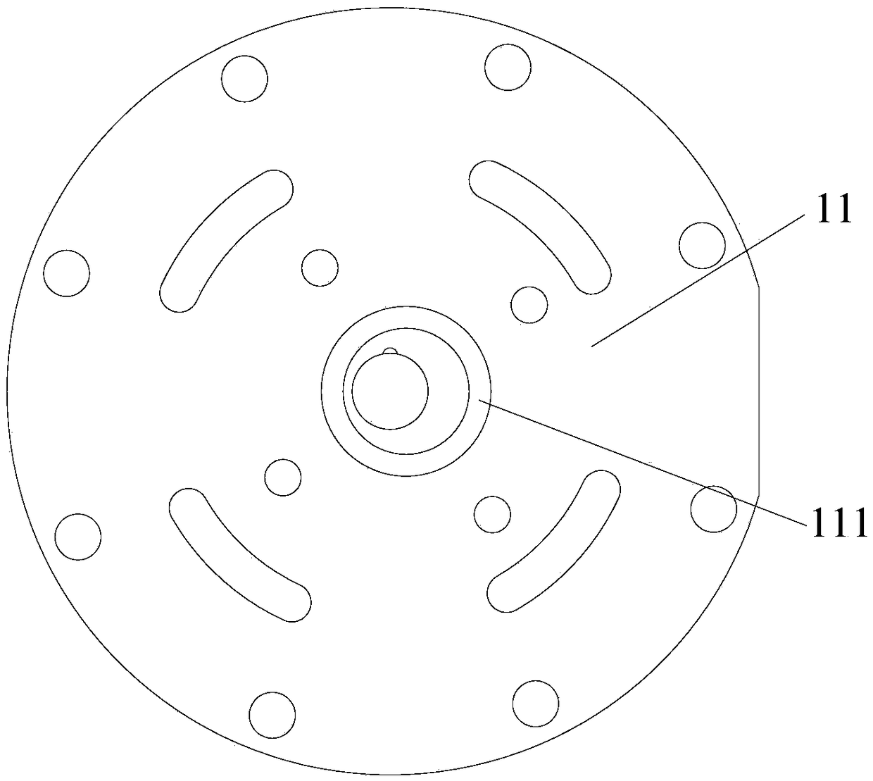
[0062] Such as figure 1 and figure 2 As shown, the pump body assembly includes an upper flange 11, an upper limit plate 14, a cylinder 20 and a piston assembly. Wherein, the upper limit plate 14 is located between the upper flange 11 and the cylinder 20 . The piston assembly is arranged in the cylinder 20, the piston assembly includes a piston sleeve 40 and a piston 50 slidingly arranged in the piston sleeve 40, the upper end surface of the piston sleeve 40 has a first extension 41, and the first extension 41 extends into the upper limit plate 14 The center hole and the lower end surface of the upper flange 11 are spaced to prevent displacement of the piston sleeve 40 relative to the upper flange 11 in the radial direction.

[0063] Applying the technical solution of this embodiment, during the operation of the pump body assembly, the first extension 41 of the piston sleeve 40 protrudes into the center hole of the upper limit plate 14 and cooperates with the lower end surfa...

Embodiment 2

[0078] The difference between the pump body assembly in the second embodiment and the first embodiment is that the structures of the upper flange 11 and the lower flange 12 are different.

[0079] Such as Figure 5 to Figure 8 As shown, the lower end surface of the upper flange 11 has a limiting portion 112 extending toward the piston sleeve 40, and the limiting portion 112 and the first extension portion 41 limit the stop to prevent the piston sleeve 40 from radially occurring relative to the upper flange 11. displacement in the direction. During the operation of the pump body assembly, the side surface of the first extension part 41 and the side surface of the limit part 112 can be limited and fitted to prevent radial displacement between the two, thereby preventing the piston sleeve 40 from occurring relative to the upper flange 11. The displacement in the radial direction ensures the stable operation of the piston sleeve 40 and improves the operational reliability and wor...

Embodiment 3

[0088] The difference between the pump body assembly in the third embodiment and the second embodiment is that the structure of the lower flange 12 is different.

[0089] Such as Figure 9 to Figure 12 As shown, the pump body assembly also includes a lower flange 12 located below the piston assembly. The surface of the lower flange 12 facing the piston sleeve 40 has a second limiting groove 121, and the limiting protrusion 43 extends into the second limiting groove. 121 to prevent radial displacement of the piston sleeve 40 relative to the lower flange 12 . In this way, the lower flange 12 cooperates with the position-limiting protrusion 43 of the piston sleeve 40 in a position-limiting manner, so as to limit the position of the piston sleeve 40 in the radial direction. At the same time, the upper end of the piston sleeve 40 is limited and supported by the upper flange 11, so that the upper and lower ends of the piston sleeve 40 are limited and supported, so as to avoid struc...


PUM


Abstract

The invention provides a pump body assembly, a fluid machine and heat-exchange equipment. The pump body assembly comprises an upper flange, an upper limiting plate, an air cylinder and a piston assembly, wherein the upper limiting plate is located between the upper flange and the air cylinder; the piston assembly is arranged in the air cylinder and comprises a piston sleeve and a piston slidably arranged in the piston sleeve; and a first extending part is arranged on the upper end surface of the piston sleeve, stretches into a center hole of the upper limiting plate and is in limiting fit withthe lower end surface of the upper flange, so that the piston sleeve is prevented from displacing in the radial direction relative to the upper flange. According to the pump body assembly, the fluidmachine and the heat-exchange equipment provided by the invention, the problem that in the prior art, the working efficiency of apump body assembly is affected since apiston sleeve of the pump body assembly is easy to eccentrically rotate is effectively solved.

Description

technical field [0001] The invention relates to the technical field of pump body components, in particular to a pump body component, fluid machinery and heat exchange equipment. Background technique [0002] At present, during the operation of the pump body assembly, the piston sleeve is prone to eccentricity and tilt rotation, which causes the piston sleeve to easily rub against the cylinder and the piston, seriously affecting the working efficiency and performance of the pump body assembly. Contents of the invention [0003] The main purpose of the present invention is to provide a pump body assembly, fluid machinery and heat exchange equipment to solve the problem in the prior art that the piston sleeve of the pump body assembly is prone to eccentric rotation and affects the working efficiency of the pump body assembly. [0004] In order to achieve the above object, according to one aspect of the present invention, a pump body assembly is provided, including: an upper f...

Claims


Application Information

Patent Timeline
Patent Type & Authority Applications(China)
IPC IPC(8): F04C18/00F04C29/00
CPCF04C18/00F04C29/00F04C2240/60F04C2240/20F04C2240/10F04C2240/80
Inventor 魏会军徐嘉杜忠诚李直杨森梁社兵任丽萍张荣婷史正良刘喜兴
Owner GREE ELECTRIC APPLIANCES INC
Why Eureka
Try Eureka