A shock absorbing device for new energy vehicles that is easy to install

A technology of new energy vehicles and shock absorbing devices, which is applied in the direction of spring/shock absorber, magnetic spring, non-rotational vibration suppression, etc. It can solve problems such as large error in measurement results, affecting work, frame or shaft wear, etc., and achieve displacement Improved measurement accuracy, smooth shock absorption, and improved ride experience

Active Publication Date: 2019-12-13
RUIAN ZHAORI AUTO PARTS
View PDF9 Cites 0 Cited by
  • Summary
  • Abstract
  • Description
  • Claims
  • Application Information

AI Technical Summary

Problems solved by technology

The shock absorber is a vulnerable part during the use of the car. The quality of the shock absorber will directly affect the driving stability of the car and the life of other parts. Therefore, the shock absorber must always be in good working condition, but now Some shock absorbers may malfunction in actual use. This is mainly caused by the collision between the shock absorber and the frame or axle, which will accelerate the damage of the shock absorber and cause damage to the frame or axle in the long run. Wear and tear; the existing electromagnetic shock absorber monitors the displacement of the shock absorber through the induction element or the magnetic induction element, but the measurement result of the induction element or the magnetic induction element is easily affected by the electromagnetic coil, the error of the measurement result is relatively large, and the result is not accurate enough ; and the magnetic induction line of the electromagnetic coil causes electromagnetic interference to the surrounding electrical equipment, affecting its work

Method used


Image

  • A shock absorbing device for new energy vehicles that is easy to install
  • A shock absorbing device for new energy vehicles that is easy to install
  • A shock absorbing device for new energy vehicles that is easy to install

Examples


Embodiment Construction

[0021] The following will be combined with Figure 1 to Figure 5 The present invention is described in detail, and the technical solutions in the embodiments of the present invention are clearly and completely described. Apparently, the described embodiments are only some of the embodiments of the present invention, not all of them. Based on the embodiments of the present invention, all other embodiments obtained by persons of ordinary skill in the art without making creative efforts belong to the protection scope of the present invention.

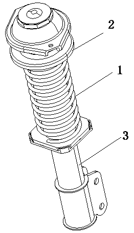
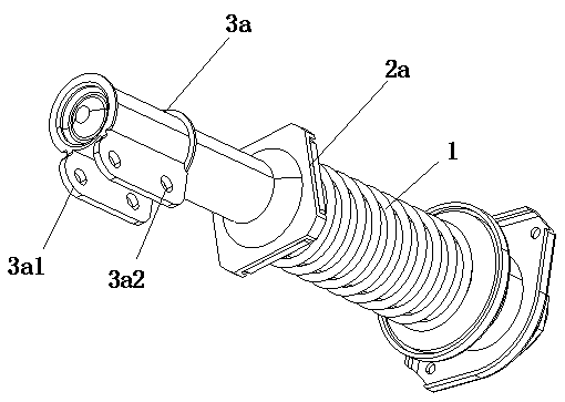
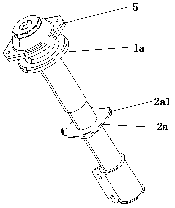
[0022] The present invention provides a kind of easy-to-install shock absorbing device for new energy vehicles through improvement, such as Figure 1-Figure 5 As shown, it includes a shock absorber 1, a first installation rod 2 and a second installation rod 3, the first installation rod 2 and the second installation rod 3 are vertically arranged and the first installation rod 2 is sleeved on the second installation rod In the rod 3, the f...


PUM


Abstract

The invention relates to the field of new energy, in particular to a damping device for a new energy vehicle and convenient to install. The damping device comprises a damping part, a first installingrod and a second installing rod. The first installing rod is sleeved with the second installing rod and a protective sleeve. A flange used for being matched with the damping part is arranged on the upper section of the first installing rod. A fixed plate matched with the damping part is fixedly connected to the upper end of the second installing rod. The first installing rod is sleeved with the damping part, and the top of the damping part abuts against the flange on the first installing rod. The bottom of the damping part is in abutting fit with the fixed plate on the second installing rod. The damping device has the beneficial effects that the first installing rod and the second installing rod are installed on the new energy vehicle and are sleeved with the damping part, and when the newenergy vehicle needs to pass through a rough road, the damping part reduces shock for the new energy vehicle and can be limited by the fixed plate on the second installing rod.

Description

technical field [0001] The invention relates to the field of new energy, in particular to a shock absorbing device for new energy vehicles that is easy to install. Background technique [0002] The road conditions that cars drive are sometimes flat, sometimes rugged and bumpy, and these different road conditions have different requirements for the speed of cars. Therefore, in the process of driving a car, in order to quickly attenuate the vibration of the frame and the body and improve the ride comfort and comfort of the car, the suspension system of the car is generally equipped with a shock absorber. The shock absorber is a vulnerable part during the use of the car. The quality of the shock absorber will directly affect the driving stability of the car and the life of other parts. Therefore, the shock absorber must always be in good working condition, but now Some shock absorbers may malfunction in actual use. This is mainly caused by the collision between the shock absor...

Claims


Application Information

Patent Timeline
Patent Type & Authority Patents(China)
IPC IPC(8): F16F6/00F16F15/04
CPCF16F6/00F16F15/04
Inventor 黄桂芳
Owner RUIAN ZHAORI AUTO PARTS
Why Eureka
Try Eureka