Display support head part connecting structure

A technology of monitor stand and connection structure, applied in the direction of machine/stand, supporting machine, mechanical equipment, etc., can solve the problem that the monitor or flat-panel TV cannot maintain a horizontal position, the monitor or flat-panel TV deviates from the horizontal state, and affects the viewing quality of TV. problems such as the aesthetic effect of the machine, to achieve the effect of maintaining long-term and stable use, low cost and good aesthetic effect

Pending Publication Date: 2018-11-13
LOCTEK ERGONOMIC TECH CORP
View PDF0 Cites 1 Cited by
  • Summary
  • Abstract
  • Description
  • Claims
  • Application Information

AI Technical Summary

Problems solved by technology

But there is a shortcoming in the display bracket head connection structure of the above prior art: generally there is no display or flat-panel TV horizontal position adjustment structure, if the bolt hole position of the wall hanging plate installed on the wall is deflected, then the display or flat-panel TV will It is impossible to maintain the horizontal position. In practice, the adjustment range of the horizontal position is not large, but it affects the viewing quality and the aesthetic effect of the TV, especially the psychological feeling of customers, that is, the customer experience.
And the existing horizontal position adjustment in the head connection structure of the display bracket of other prior art is generally the rotation adjustment that the cylinder and the hole or the ball and the hole cooperate. Relying on the central screw for positioning, its structure is more complicated, and the biggest shortcoming of the connection structure of the head of the display bracket is that the horizontal position positioning is not durable, long time or encountering vibration, etc., it is easy to produce relative rotation and make the display or flat-panel TV off-level

Method used


Image

  • Display support head part connecting structure
  • Display support head part connecting structure

Examples


Embodiment Construction

[0014] The specific embodiments of the present invention will be further described below in conjunction with the accompanying drawings. What needs to be declared here is that the descriptions of these specific implementations are used to help understand the present invention, but are not intended to limit the present invention. In addition, the technical features and technical means involved in the various specific embodiments of the present invention described below can be combined with each other as long as they do not constitute a conflict with each other.

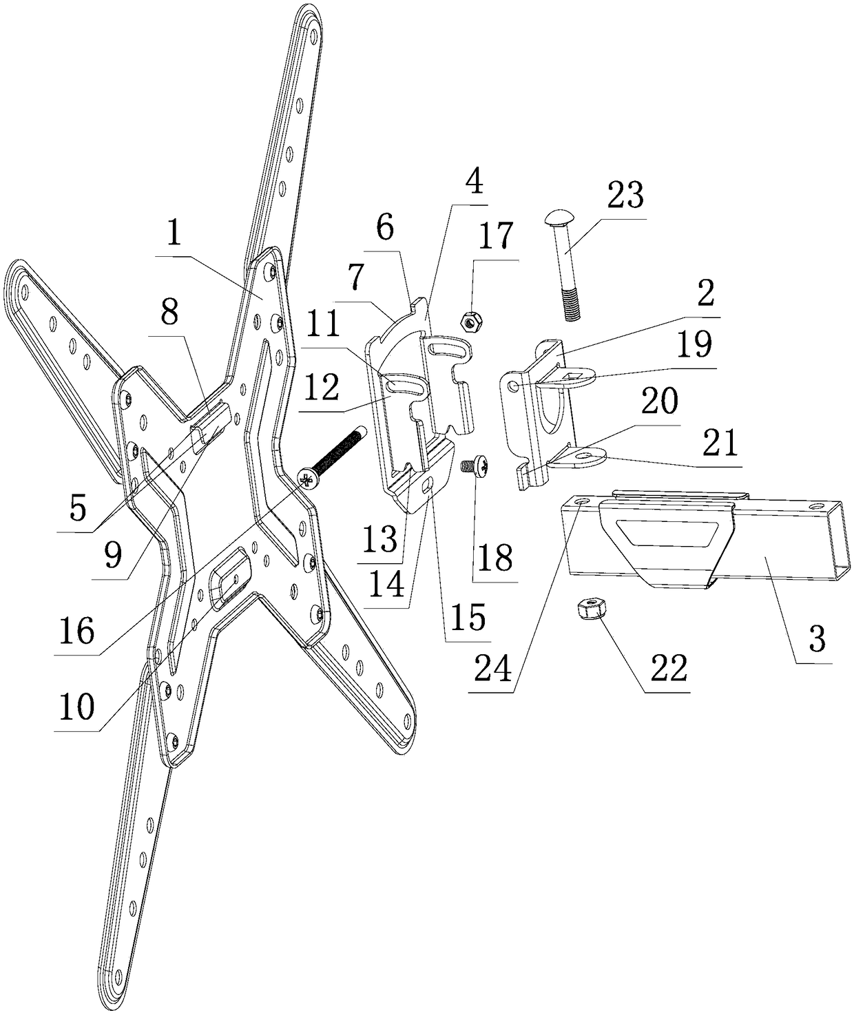
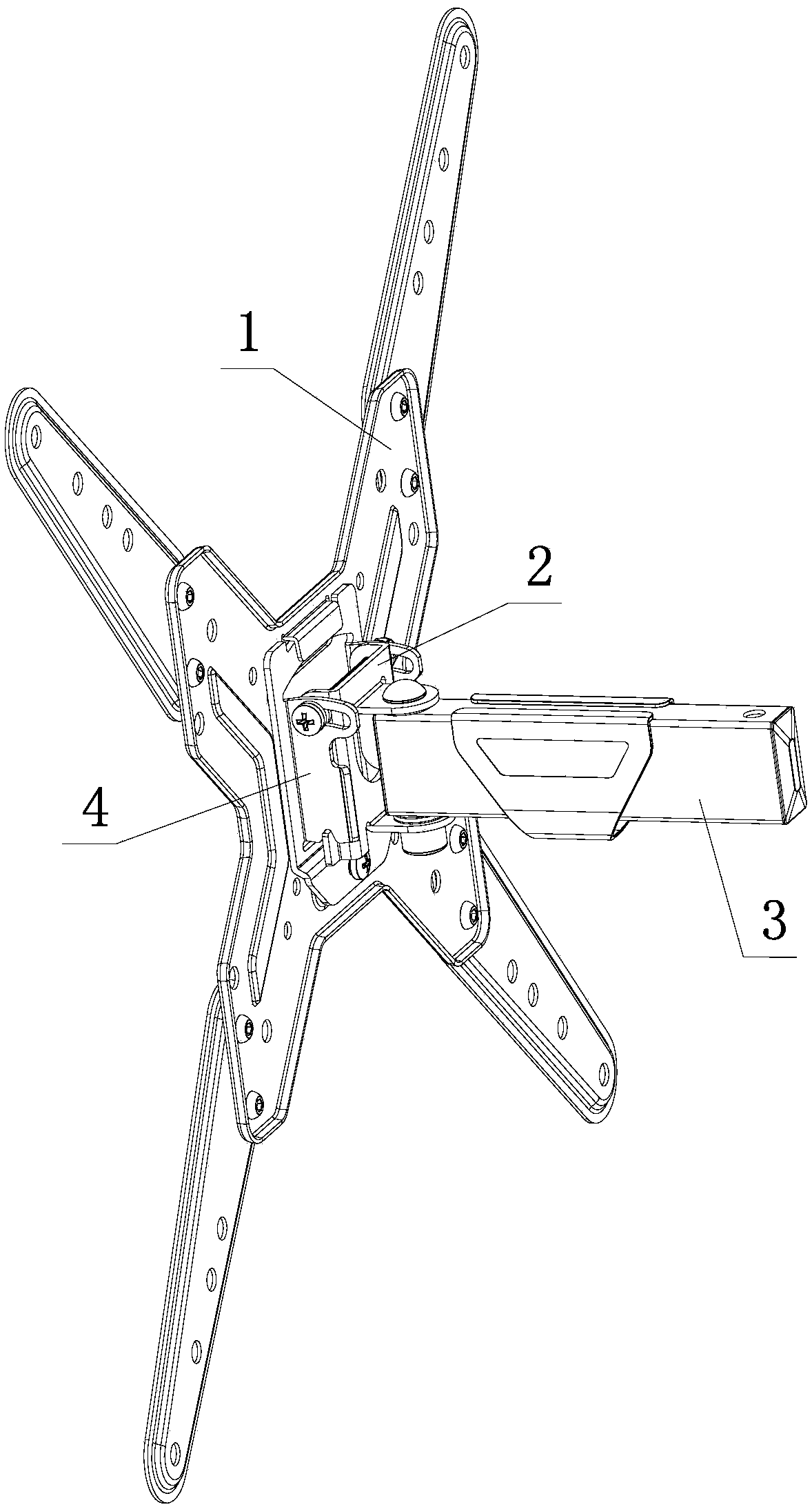
[0015] Such as figure 1 , figure 2 shown

[0016] The head connection structure of the display bracket of the present invention includes a display installation board 1 , a first connection board 2 and a connection arm 3 . As mentioned above, the division between monitor brackets and flat-panel TV racks is not very clear in the industry, and they are generally used together. Therefore, the monitor mounting plate here...


PUM


Abstract

The invention discloses a display support head part connecting structure which comprises a display installation plate, a first connecting plate, a connecting arm, and a second connecting plate. The first connecting plate is connected with the connecting arm in a horizontal swinging way; a notch for hanging a hanging plate with a hanging slot for the display installation plate is formed in the upper end of the second connecting plate; the width of the notch is larger than the width of the hanging plate; the top surface of the second connecting plate on the bottom part of the notch is an upwardsconvex arc surface; a horizontally arranged waist-shaped hole is formed in the lower end of the second connecting plate; a threaded hole for a screw to penetrate through the waist-shaped hole so as to tightly fix the lower end of the second connecting plate is formed in the display installation plate; the hanging plate and the display installation plate are of an integrated structure; the displayinstallation plate is bent upwards and then bent downwards so as to form an inverted L-shaped hanging plate with an upper baffle plate and an outer baffle plate; and the second connecting plate and the first connecting plate are connected in a perpendicular swinging way. The display support head part connecting structure is simple in structure, and the horizontal position can be adjusted quicklyand conveniently and is stable, reliable and durable.

Description

technical field [0001] The invention relates to the technical field of display brackets, in particular to a head connection structure of a display bracket. Background technique [0002] Monitor brackets and flat-panel TV racks are not clearly divided in the industry, and they are generally used together. A display stand in the prior art includes a display mounting plate, a connecting arm and a wall hanging plate. The head connection structure of the display bracket generally refers to the connection structure connecting the display mounting plate and the connecting arm. The connecting structure of the head of the display bracket in the prior art generally includes a first connecting plate, on which there are holes and bolts and nuts for adjusting the pitch angle of the display mounting plate that cooperate with the display mounting plate, and there are also bolts and nuts on the first connecting plate Holes and bolts for adjusting the horizontal swing angle of the display ...

Claims


Application Information

Patent Timeline
Patent Type & Authority Applications(China)
IPC IPC(8): F16M11/04F16M11/12F16M13/02
CPCF16M11/04F16M11/121F16M13/02
Inventor 项乐宏林涛杨飞
Owner LOCTEK ERGONOMIC TECH CORP
Why Eureka
Try Eureka