Target Extraction Method of FM Stepped Radar Signal Based on Position Calibration

A technology of radar signal and frequency modulation stepping, which is applied in the direction of measuring devices, radio wave reflection/re-radiation, instruments, etc. It can solve the problems affecting the imaging quality, jumping back and forth of the range image, and increasing the processing difficulty of the envelope alignment algorithm, etc., to achieve Simplify the imaging process and save the amount of computation

Active Publication Date: 2022-02-01
中国人民解放军63889部队
View PDF5 Cites 0 Cited by
  • Summary
  • Abstract
  • Description
  • Claims
  • Application Information

AI Technical Summary

Problems solved by technology

[0029] There is a problem: suppose the target is composed of three scattering points 1, 2, 3, such as image 3 As shown, at a certain moment, the intensity of scattering point 2 is the largest, and the corresponding distance unit positions after refinement based on the maximum value extraction method are Location_1, Location_2, and Location_3. After the intensity of scattering points fluctuates, the intensity of scattering point 1 becomes the largest. The distance image obtained after the same extraction algorithm is as follows image 3 As shown in the figure on the right, scatter point 1 is located in the middle of the distance image, and scatter points 2 and 3 jump to the right to two positions of Location_4 and Location_5
[0030] During the imaging process, the attitude of the target will always change. If the target extraction algorithm always uses the maximum value as the benchmark to determine the starting point position of the effective area, it will cause the range image to jump back and forth, which will inevitably increase the processing difficulty of the later envelope alignment algorithm and affect image quality

Method used


Image

  • Target Extraction Method of FM Stepped Radar Signal Based on Position Calibration
  • Target Extraction Method of FM Stepped Radar Signal Based on Position Calibration
  • Target Extraction Method of FM Stepped Radar Signal Based on Position Calibration

Examples


Embodiment Construction

[0061] The preferred embodiments of the present invention will be described below in conjunction with the accompanying drawings. It should be understood that the preferred embodiments described here are only used to illustrate and explain the present invention, and are not intended to limit the present invention.

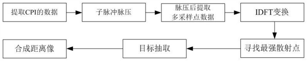
[0062] A method for extracting a frequency modulation stepping radar signal target based on position calibration, comprising the following steps:

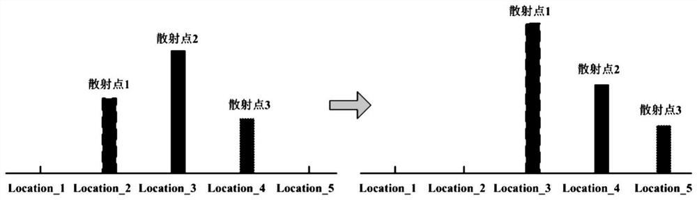
[0063] (1) For each group of CPI echo data, take a certain scattering point in the thinned range image as the object, calibrate its real-time position value, and use this as a reference to determine the starting point position P for extracting the effective area 0 ;The distance image obtained by this method has already aligned the same scattering point in the same distance unit, and there is no need for envelope alignment in two-dimensional imaging, which reduces the amount of imaging calculations and helps to improve the...


PUM


Abstract

The invention discloses a method for target extraction of frequency modulation stepping radar signals based on position calibration, which comprises the following steps: (1) for each group of CPI echo data, take a certain scattering point in the refined range image as the object; Calibrate its real-time position value, and use this as a benchmark to determine the starting point position P of the effective area for extraction 0 ; The distance image obtained by this method has already aligned the same scattering point into the same distance unit, and no envelope alignment is required during two-dimensional imaging, which reduces the amount of imaging computation and helps to improve the quality of post-mortem imaging; (2) According to The refinement results of part of the CPI echo data estimate the target motion speed, according to the speed value and the first P 0 The value determines the following P 0 ; Due to the error in the speed estimation, the subsequent tasks require envelope alignment to improve the alignment accuracy, but the processing difficulty is relatively reduced, and the accuracy will be improved.

Description

technical field [0001] The invention relates to a method for extracting a frequency modulation stepping radar signal target based on position calibration. Background technique [0002] The stepped frequency signal synthesizes a wideband signal by transmitting an instantaneous narrowband signal, thereby obtaining a high-resolution radar signal. The specific method is that the radar emits a group of pulses, the carrier frequency of which changes linearly, trades time for a large bandwidth, and finally forms a high-resolution two-dimensional image through signal processing. Therefore, this signal is especially suitable for narrowband radar, and has low requirements on radar hardware such as receiver and A / D sampling, so it has been widely used in the fields of identification and radar imaging. The linear frequency modulation step frequency radar signal is a kind of step frequency signal, the difference is that the sub-pulse adopts chirp signal, compared with the conventional s...

Claims


Application Information

Patent Timeline
Patent Type & Authority Patents(China)
IPC IPC(8): G01S7/41G01S13/50
CPCG01S7/415G01S13/50
Inventor 周志增刘洪亮刘朋丁桂强王永海顾荣军王四倍
Owner 中国人民解放军63889部队
Why Eureka
Try Eureka