
Very simple floating magnetic control memcapacitor circuit simulation model

A circuit simulation and memory capacitor technology, applied in the fields of instruments, electrical digital data processing, computing, etc., can solve the problems that the two-port voltage cannot exceed the supply voltage, the component structure is complex, and is not a two-port model, so as to achieve the change of the memory capacity value. Flexibility in scope, reduced complexity and component count, no ground-limiting effects

Active Publication Date: 2018-11-13
CHENGDU NORMAL UNIV
View PDF9 Cites 3 Cited by
  • Summary
  • Abstract
  • Description
  • Claims
  • Application Information

AI Technical Summary

Problems solved by technology

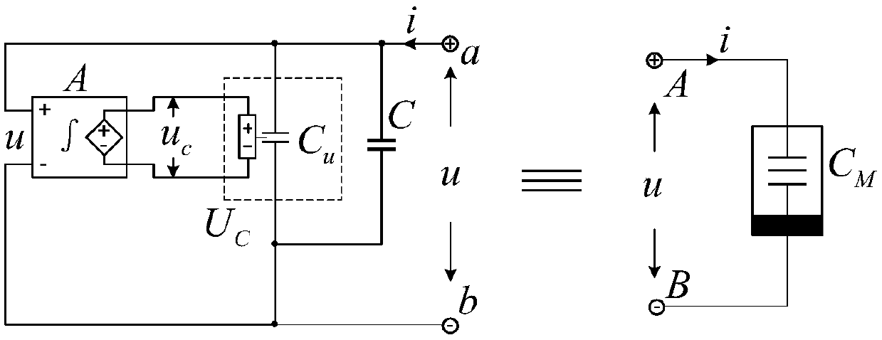
[0004] The technical problem to be solved by the present invention is to provide an extremely simple floating magnetron memcapacitor circuit simulation model, which solves the problem that the existing magnetron memcapacitor circuit simulation model needs one end to be grounded, is not a two-port model, and the voltage of the two ports cannot exceed the value in the model. The power supply voltage of the source device and the complex structure of the required components

Method used


Image

  • Very simple floating magnetic control memcapacitor circuit simulation model
  • Very simple floating magnetic control memcapacitor circuit simulation model
  • Very simple floating magnetic control memcapacitor circuit simulation model

Examples


Embodiment Construction

[0013] The principles and features of the present invention are described below in conjunction with the accompanying drawings, and the examples given are only used to explain the present invention, and are not intended to limit the scope of the present invention.

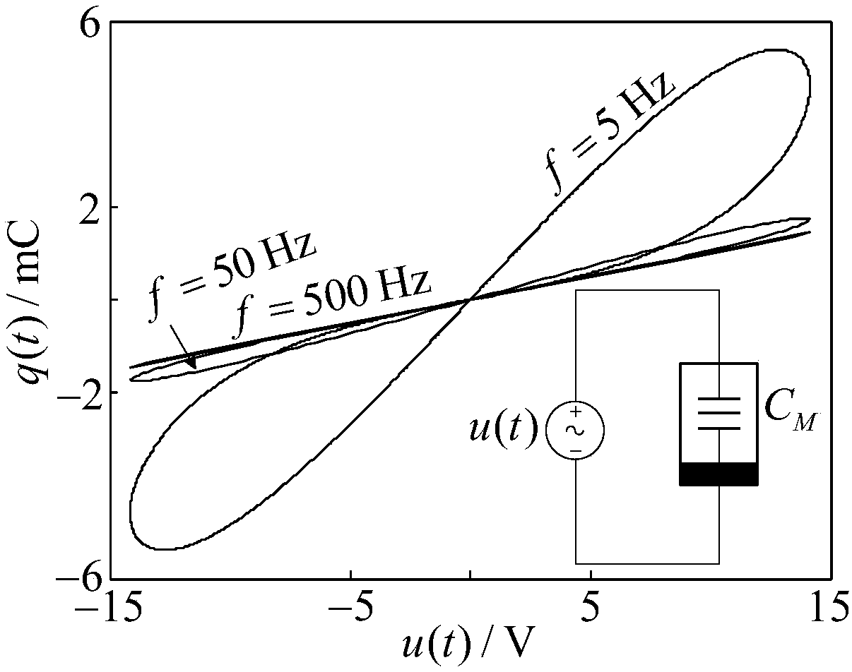
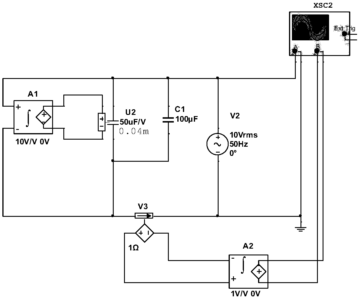
[0014] Such as figure 1 As shown, a minimalist floating magnetron memcapacitor circuit simulation model, including port a, port b, voltage-controlled capacitor U C , capacitor C and voltage integrator A, voltage-controlled capacitor U C Including the voltage control terminal u c and controlled capacitance C u , the voltage-controlled capacitor U C Internal controlled capacitance C u The capacitance of the voltage control terminal u c The voltage value control, the voltage integrator A includes the voltage input terminal u and the voltage output terminal u c , the voltage-controlled capacitor U C Internal controlled capacitance C u They are respectively connected in parallel with capacitor C and the voltage i...


PUM


Abstract

The invention discloses a very simple floating magnetic control memcapacitor circuit simulation model which comprises a port a, a port b, a voltage controlled capacitor UC, a capacitor C and a voltageintegrator A. The voltage controlled capacitor UC comprises a voltage control end uc and a controlled capacitor Cu; a capacitance of the controllable capacitor Cu in the voltage controlled capacitorUC is controlled by a voltage value of the voltage control end uc; and the voltage integrator A comprises a voltage input end u and a voltage output end uc. Electrical characteristics of the ports a and b of the floating magnetic control memcapacitor circuit simulation model are equivalent to characteristics of A and B ports of a magnetic control memcapacitor CM, only needs to use existing three elements in simulation software, and is a two-port model; complexity and the element number of an existing magnetic control memcapacitor circuit simulation model are further reduced; and the very simple floating magnetic control memcapacitor circuit simulation model has the advantages of flexible memcapacitative value changing range, no grounding limitation, wide working voltage range and easinessfor understanding.

Description

technical field [0001] The patent of the present invention relates to the field of new circuit element model construction, in particular to a minimalist floating magnetron memcapacitor circuit simulation model. Background technique [0002] In 1971, Professor Cai Shaotang, the "father of memristors", theoretically proposed a memristor (memristor) that could describe the relationship between magnetic flux and charge. In 2008, after Hewlett-Packard Labs announced in the journal "Nature" that it had physically realized a two-terminal device with the characteristics of a memristor, new concepts of memcapacitor and meminductor were also proposed one after another. Memcapacitors, memristors, and memristors all have memory functions, showing pinch hysteresis loops with contraction hysteresis characteristics. Unlike memristors, memcapacitors and memristors do not need to consume energy during operation. In low-power VLSI, memcapacitors and memristors have more advantages than memri...

Claims


Application Information

Patent Timeline
IPC IPC(8): G06F17/50
CPCG06F30/367Y02E40/30
Inventor 余波
Owner CHENGDU NORMAL UNIV
Learn More