AI technical title is built by Patsnap AI team. It summarizes the technical point description of the patent document.
A disc rotor and rotor support technology, applied in the field of motor parts, can solve problems such as difficulty in fixing a ring 10-shaped iron core 1 and a permanent magnet 9, etc.
Pending Publication Date: 2018-11-13
SHANGHAI PANGOOD POWER TECH CO LTD
View PDF10 Cites 7 Cited by
Summary
Abstract
Description
Claims
Application Information
AI Technical Summary
This helps you quickly interpret patents by identifying the three key elements:
Problems solved by technology
Method used
Benefits of technology
Problems solved by technology
[0004] However, in actual use, the permanent magnet 9 and the ring-shaped iron core 1 will be subjected to a huge axial magnetic pulling force from the stator core, making it difficult for the rotor assembly to fix the ring 10-shaped iron core 1 and the permanent magnet 9 in the axial direction
Method used
Image
Click on the blue label to locate the original text in one second.
Reading with bidirectional positioning of images and text.
Examples
Embodiment 1
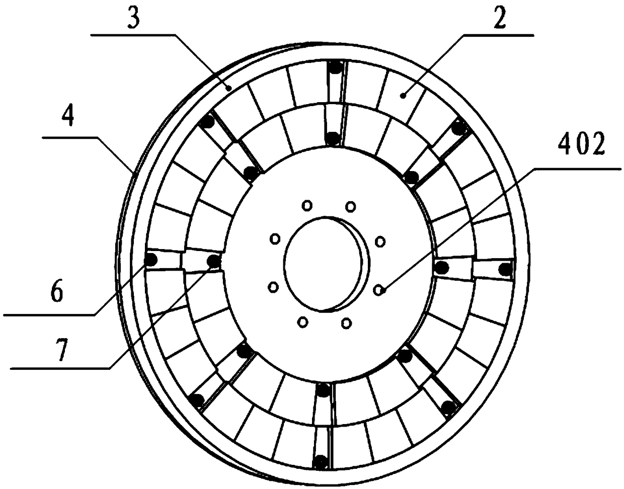
[0057] Such as Figure 2-4 As shown, the present invention provides a disc rotor. The disc rotor structure can be used in the middle stator, two side rotors or single stator, single rotor or cascaded disc motor structures.
[0058] Wherein, the disc rotor includes an annular iron core 1 , a magnetic steel 2 , a hoop 3 and a rotor bracket 4 .
[0059] The annular iron core 1 is formed by winding silicon steel sheet or amorphous. The annular iron core 1 is provided with a plurality of sets of magnetic steel mounting positions 101, the same set of magnetic steel mounting positions 101 are installed with the same magnetic pole magnets 2, and the adjacent sets of magnetic steel mounting positions 101 are equipped with opposite magnetic pole magnets 2. A buckle device 102 is provided on the magnetic steel mounting position 101 .
[0060] The magnet 2 is installed in the magnet installation position 101 , and the buckle device 102 can buckle the magnet 2 in the magnet installation...
Embodiment 2
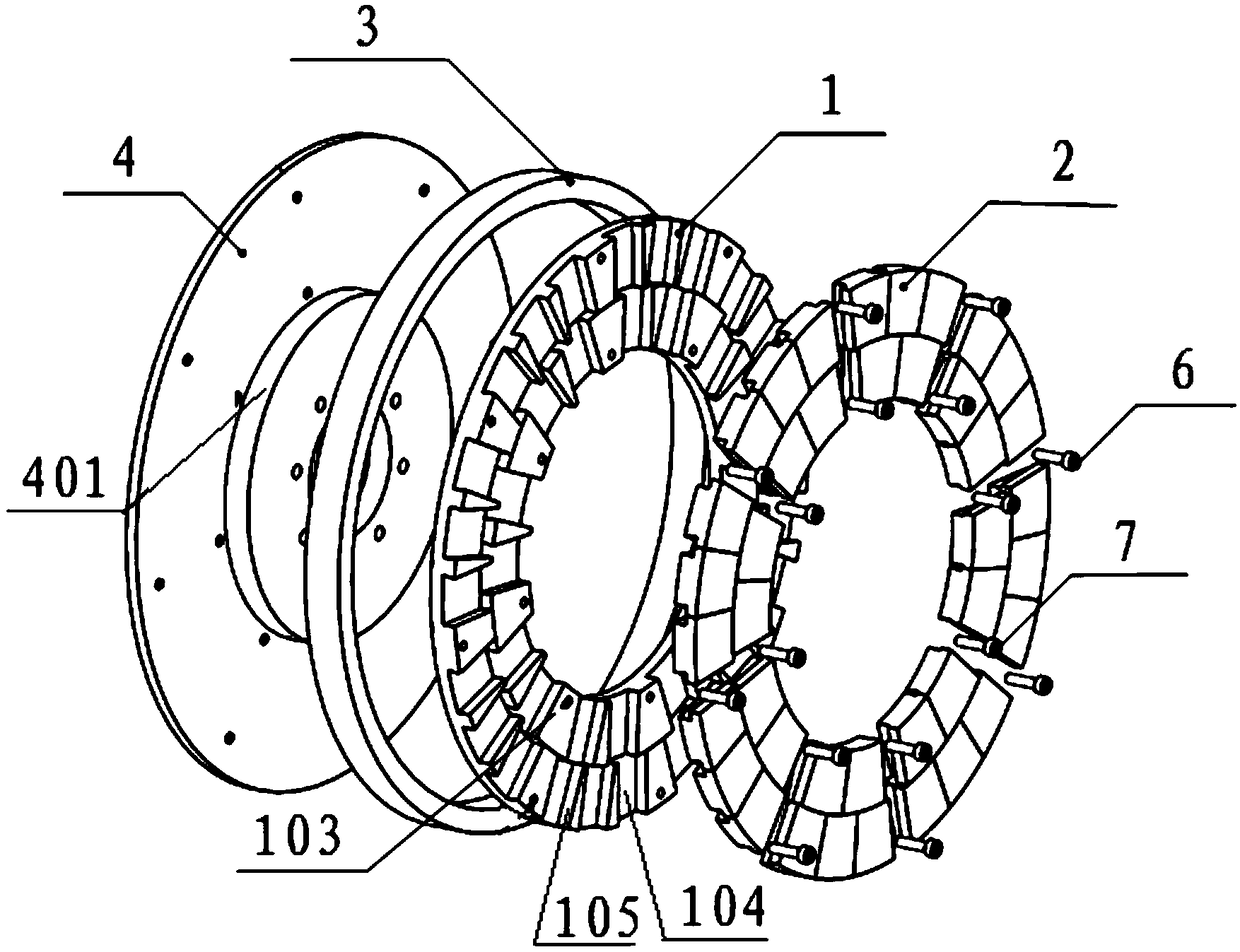
[0065] Such as Figure 5-10 , in the second embodiment provided by the present invention, the structure of the disc rotor in this embodiment is similar to that in the first embodiment, and the similarities will not be repeated, and only the differences will be introduced.
[0066] In this embodiment, the present invention specifically discloses that the annular iron core 1 is provided with first iron core teeth 103 , and the number of the first iron core teeth 103 is multiple, which are used to separate multiple groups of magnetic steel installation positions 101 .
[0067] The present invention discloses two methods for fixing the annular iron core 1 on the rotor bracket 4:
[0068] (1) Open a through hole on the first iron core tooth 103, and fix the annular iron core 1 on the rotor bracket 4 by the first screw 6;
[0069] (2) The disc rotor also includes a claw-shaped support 5, the claw-shaped support 5 includes an annular support portion 501 and a support rib 502, the an...
Embodiment 3
[0096] The present invention provides a disc motor, including the disc rotor in any one of the above embodiments.
PUM
Abstract
The invention discloses a disc rotor and a disc motor. The disc rotor comprises a ring iron core which is provided with multiple sets of magnetic steel installing positions, wherein the magnetic steelinstalling positions are provided with buckle devices; magnetic steel which is installed in the magnetic steel installing positions and can be buckled in the magnetic steel installing positions by the buckle devices; a ring hoop which sleeves the outer circle of the ring iron core and is connected with the outer circumferential surface in an abutting way; and a rotor support which is provided with a ring boss which is inwardly sleeved in the inner circle of the ring iron core and connected with the inner circumferential surface in an abutting way, wherein the ring iron core is connected withthe rotor support through first screws. The ring iron core is fixed on the rotor support through the first screws and the rotor support axially limits the ring iron core so as to prevent axial displacement under the axial tension of the stator iron core. Besides, the buckle devices are arranged in the magnetic steel installing positions and the buckle devices can buckle the magnetic steel in the magnetic steel installing positions so as to prevent axial displacement of the magnetic steel.
Description
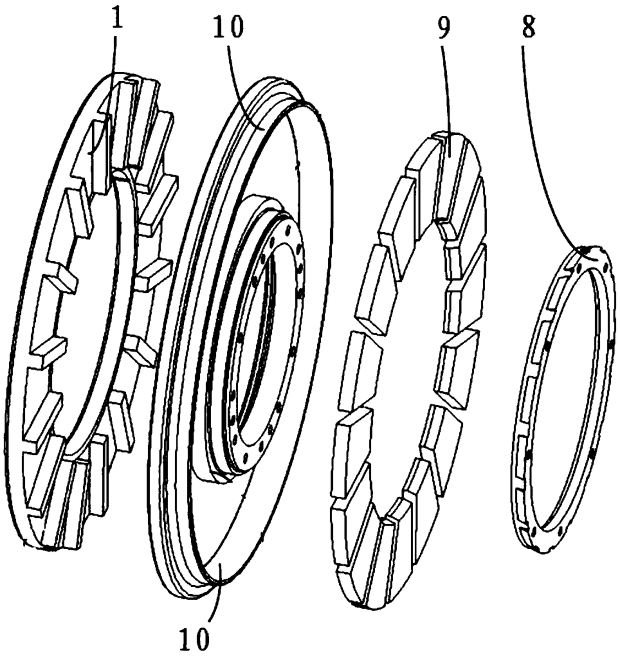
technical field [0001] The invention relates to the technical field of motor components, in particular to a disc rotor and a disc motor. Background technique [0002] Radial field motors and axial field motors (also called disc motors) are two major branches of the motor field. Disk motors are more and more widely used because of their higher iron core utilization, higher power density and higher torque density. [0003] At present, the rotor assembly of a disc motor is mainly composed of a rotating self-supporting disc 8, an annular iron core 1, a permanent magnet 9 and a fixed ring 10, such as figure 1 shown. The permanent magnet 9 is installed in the steel groove of the annular iron core 1 , and the support disc 8 and the fixed ring 10 are respectively installed on the inner and outer sides of the annular iron core 1 to limit the radial direction of the permanent magnet 9 . [0004] However, in actual use, the permanent magnet 9 and the ring core 1 will be subjected to...
Claims
Application Information
Patent Timeline
Application Date:The date an application was filed.
Publication Date:The date a patent or application was officially published.
First Publication Date:The earliest publication date of a patent with the same application number.
Issue Date:Publication date of the patent grant document.
PCT Entry Date:The Entry date of PCT National Phase.
Estimated Expiry Date:The statutory expiry date of a patent right according to the Patent Law, and it is the longest term of protection that the patent right can achieve without the termination of the patent right due to other reasons(Term extension factor has been taken into account ).
Invalid Date:Actual expiry date is based on effective date or publication date of legal transaction data of invalid patent.

