Lighting system, lighting device and control method thereof

A technology of a lighting device and a control method, applied in the field of lighting systems, can solve the problems of unfavorable wide application and high cost, and achieve the effects of convenient perception, reduced requirements, and convenient intuition

Inactive Publication Date: 2018-11-13
PANASONIC INTELLECTUAL PROPERTY MANAGEMENT CO LTD
View PDF0 Cites 2 Cited by
  • Summary
  • Abstract
  • Description
  • Claims
  • Application Information

AI Technical Summary

Problems solved by technology

Moreover, for appliances that are not particularly "smart" such as air purifiers, it is necessary to configure hardware and software at the same time to realize the above functions, and the cost is relatively high, which is not conducive to its wide application.

Method used


Image

  • Lighting system, lighting device and control method thereof
  • Lighting system, lighting device and control method thereof
  • Lighting system, lighting device and control method thereof

Examples


Embodiment approach 1

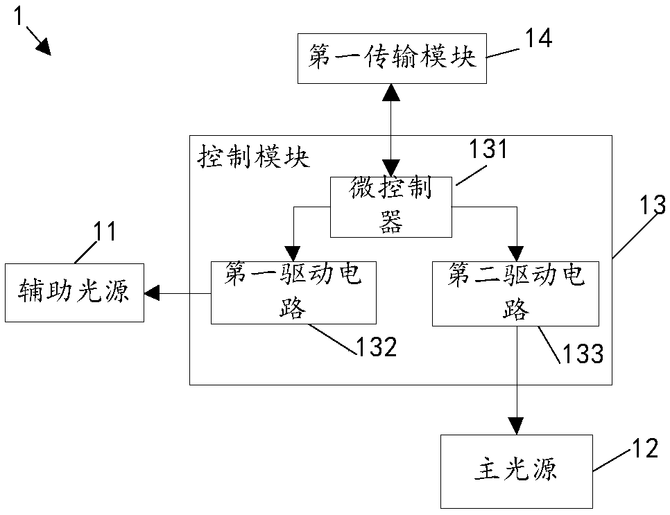
[0031] The first embodiment of the present invention provides a lighting device. Such as Figure 1A As shown, the lighting device 1 includes an auxiliary light source 11 for realizing the prompt function, a main light source 12 for realizing the lighting function, a control module 13 and a first transmission module 14; the control module 13 is connected to the main light source 12, the auxiliary light source 11 and the The first transmission module 14 . Wherein, the lighting device also includes a clock circuit (not shown in the figure) and other circuits for assisting the normal operation of the control module. The content of this part should belong to the well-known technology in the art, and will not be described in detail here.

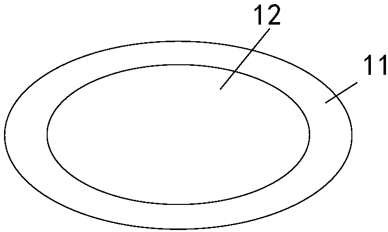
[0032] In this example, if Figure 1B As shown, the auxiliary light source 11 is arranged around the periphery of the main light source 12 in the form of a light strip. In one example, such as Figure 1B Among them, the main light source 12 is ...

Embodiment approach 2

[0042] A second embodiment of the present invention provides a lighting device. The second embodiment is improved on the basis of the first embodiment, the main improvements are as follows: figure 2 As shown, the lighting device 1 further includes a mode switching switch 15, which is connected to the control module 13 and is used for operation by a user to switch the working mode of the lighting device.

[0043] Specifically, the mode switching switch 15 may be a mechanical switch, for example, the mechanical switch may be installed on a wall, and connected to the microcontroller 131 in the control module 13 through wiring. The user can switch the working mode of the lighting device by operating the mechanical switch. Wherein, the working mode includes at least an information prompt mode and a main lighting mode, but is not limited thereto. In one example, the mechanical switch includes a first switch and a second switch, respectively corresponding to the information prompt...

Embodiment approach 3

[0049] The third embodiment of the present invention provides a lighting device. The third embodiment is improved on the basis of the second embodiment. The main improvements are as follows: image 3 As shown, the lighting device 1 further includes a memory 16 connected to the control module 13 and at least storing the last lighting mode of the auxiliary light source 11 .

[0050] Specifically, the memory 16 is connected to the microcontroller in the control module 13, and the memory 16 at least stores the lighting mode of the auxiliary light source when the lighting device 1 was turned off last time. When the control module 13 does not receive the data representing the information to be prompted, it can access the memory 16 to obtain the last lighting mode of the auxiliary light source 11 from the memory 16, and control the auxiliary light source to emit light according to the obtained last lighting mode.

[0051] For example, after the lighting device is powered on, or after...


PUM


Abstract

The invention belongs to the lamp control technical field and discloses a lighting system, a lighting device and a control method thereof. The lighting device comprises a main light source, an auxiliary light source, a control module and a first transmission module; the control module is connected with the main light source and is used for controlling the light emission of the main light source; the control module is further connected with the auxiliary light source and the first transmission module; the control module is further used for controlling the light emission mode of the auxiliary light source according to data characterizing information to be prompted when receiving the data characterizing information to be prompted through the first transmission module. The invention also provides a lighting system and a control method of the lighting device. With the lighting system, lighting device and control method thereof provided by the embodiments of the invention adopted, a novel information prompting method which is more convenient for a user to perceive more directly is provided; and the requirements of an intelligent terminal for hardware and software configuration can be lowered, and the monitoring of the health of the user or environmental conditions can be realized through more terminals or electrical devices.

Description

technical field [0001] The invention relates to the technical field of lamp control, in particular to a lighting system, a lighting device and a control method thereof. Background technique [0002] With the development of intelligent technology and people's emphasis on the concept of health, the hardware configuration of various intelligent terminals is constantly enriched to realize the monitoring of their own health or environmental conditions. For example, many mobile phones or wearable devices are equipped with at least one biometric information collector to collect the user's biometric data or motion data, and then the processor in the smart terminal performs statistics and analysis on the collected data, and through the smart terminal The configured prompt device will prompt to inform the user of the analysis result. [0003] Therefore, in addition to supporting related hardware (such as information collectors, prompting devices, etc.), such smart terminals often als...

Claims


Application Information

Patent Timeline
IPC IPC(8): H05B37/02
CPCH05B47/10H05B47/19Y02B20/40
Inventor 陈永虎大谷秀雄武可
Owner PANASONIC INTELLECTUAL PROPERTY MANAGEMENT CO LTD
Why Eureka
Try Eureka