
Trenching frame for trenching machine

A trencher and fixing frame technology, applied in agricultural machinery and implements, excavation/covering trenches, applications, etc., can solve problems such as bending and breaking of hard objects of plow tools, and achieve the effect of facilitating later construction and avoiding economic losses

Inactive Publication Date: 2018-11-16
WENZHOU POLYTECHNIC
View PDF5 Cites 0 Cited by
  • Summary
  • Abstract
  • Description
  • Claims
  • Application Information

AI Technical Summary

Problems solved by technology

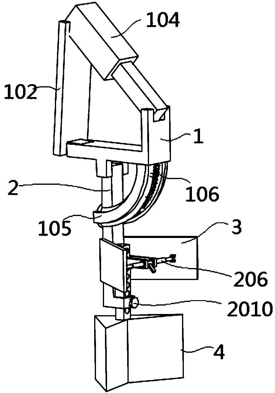
[0003] The purpose of the present invention is to provide a ditching frame for a ditching machine, which applies a supporting force to the support bar through a spring, and the support bar is compressed by an external force to effectively protect the plow tool and solve the problem of the plow tool hitting hard objects. The problem of bending and breaking

Method used


Image

  • Trenching frame for trenching machine
  • Trenching frame for trenching machine
  • Trenching frame for trenching machine

Examples


Embodiment Construction

[0025] The following will clearly and completely describe the technical solutions in the embodiments of the present invention with reference to the accompanying drawings in the embodiments of the present invention. Obviously, the described embodiments are only some, not all, embodiments of the present invention. Based on the embodiments of the present invention, all other embodiments obtained by persons of ordinary skill in the art without creative efforts fall within the protection scope of the present invention.

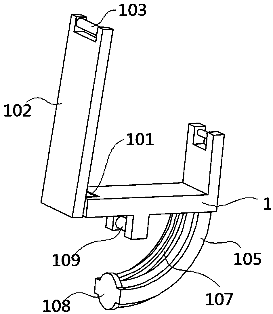
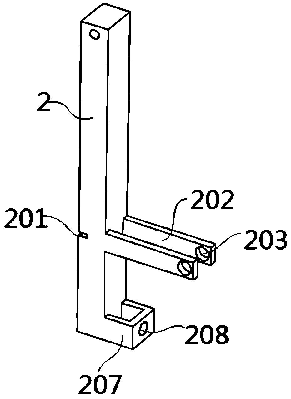
[0026] see Figure 1-6 As shown, the present invention is a ditching frame for a ditching machine, comprising a fixed frame 1, characterized in that: the bottom of the fixed frame 1 is hinged with a support rod 2; both sides of the support rod 2 are hinged with a dividing soil plate 3; The plow tool 4 is fixed on one end of the rod 2; the first hinge seat 101 is fixed on the surface of the fixed plate 1; the support plate 102 is hinged on the first hinge seat 101; ...


PUM


Abstract

The invention discloses a trenching frame for a trenching machine and relates to the technical field of agricultural machinery. The trenching frame comprises a fixed frame; a supporting rod is hingedto the bottom of the fixed frame; soil dividing plates are hinged to the two side surfaces of the supporting rod; a plow is fixed on one end surface of the supporting frame; a bent pipe is fixed on one surface of the fixed plate; a spring is sheathed on the inner surface of the bent pipe; a notch is formed in the circumferential side surface of the bent pipe; a limiting plate is fixed on one end surface of the bent pipe; a third hinge seat is fixed on one surface of the fixed plate and is hinged to the supporting rod; two first connecting rods are fixed on one side surface of the supporting rod; a through hole is formed in one surface of each of the two first connecting rods; a ball bearing is fixed on the inner surface of the through hole; a threaded sleeve is fixed on the inner surface of the ball bearing. The trenching frame disclosed by the invention has the benefits that by rotary fit between the supporting rod and the fixed frame, the spring in the bent pipe applies a supportingforce to the supporting rod, and the spring is compressed by the external force applied on the supporting rod, so that the plow can be effectively protected, therefore, the economic loss is avoided, and the smooth trenching operation is facilitated.

Description

technical field [0001] The invention belongs to the technical field of agricultural machinery, in particular to a ditching frame for a ditching machine. Background technique [0002] Most of the existing trenchers are to install the trenching frame at the rear of the small tractor, and the output power of the tractor drives the plow to carry out trenching. When using a plow for ditching, if it hits tree roots or other hard objects buried in the field soil, it is easy to cause the plow to bend or even break, which not only brings economic losses, but also affects the progress of ditching; And the soil dividing plate on the existing ditching frame is generally set to be fixed, and when the throwing distance of the soil dividing plate is too short, it is easy to enter the groove, and when the distance is too far, it is easy to enter the adjacent groove. In the middle, it is not convenient for later construction. Contents of the invention [0003] The purpose of the present ...

Claims


Application Information

Patent Timeline
Patent Type & Authority Applications(China)
IPC IPC(8): A01C5/06A01B59/00
CPCA01B59/00A01C5/062
Inventor 朱雷鸣
Owner WENZHOU POLYTECHNIC
Learn More